This IMCA modified has run at San Jose, Watsonville, Antioch, Petaluma, and most recently at Merced Speedway in the Central Valley of California. Fowler Automotive has been involved with the car over seven racing seasons providing engine service originally; and in the last five , complete assemblies. Jim Pennington is the car owner and has chosen to run an all-Ford drive train based on a Windsor 351 CID block. Cleveland heads are substantially reworked as are the much longer connecting rods. At various times Fowler Automotive also provided shop space for weigh-in adjustments and wheel alignment. In 1997 the car won several heat races, a main event, and lead many laps. It almost always finished in the top five or spun out while leading... the team had a new driver that year, Brett Montana. In 1998 we again had several new drivers, Galen Carrera, who ran mini sprints at north bay tracks in prior years. Daren Pennington who had raced dirt Karts with some success, and John Kirkpatrick who wanted to move up from entry level stock cars. For 1999 John Kirkpatrick drove (rookie year). He finished 8th at Merced and 19th in the five state IMCA Western Region. In 23 starts I believe he won more heats than any other driver at Merced, three trophy dashes and had a 3rd place as his best finish. In 2000 the car was stored pending a sale that never materialized. For the 2001 season Jim Pennington drove for fun as his time and finances allowed. The sponsors of Jim Pennington Racing are Blossom Valley UNOCAL and Fowler Automotive. Central Tools in Sunnyvale, Monsters of Rock, Bradley Nameplate of Fremont CA, and Custom Alignment of Mtn. View CA. helped out in prior years. Ray Jacobson at Tuban Industrial Products, Mtn. View has provided invaluable help with the Ford combination. Bill Jones of Taylorsville Utah and Kelly Owen of Santa Clara were great technical advisers.
Jim Pennington was president of X-act Computer Service located in
Sunnyvale until his passing in 2003. My understanding is the car was
sold several years later and it's spare engines were sold separately. I
have some parts and build / tech specifications for them if the new
owners need service.

Hayos Racing
Hayos Racing has been running a Toyota Truck in various configurations for many years.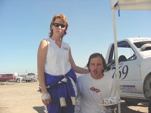
They have won several regional championships and gained considerable respect for fair and even handed competition. Their teams history can be followed at Hayos Motor sports I started helping their team with technical questions in 2003 regarding their 22 R based race engine and some tuning issues. That lead to further involvement until in 2006 the truck was switched to a V-6 engine based off a 5V-FE Toyota product converted to racing use by a prominent north Bay Area shop. That engine was rebuilt in my shop to reverse engineer it's secrets, document it's parts list, and prove it's horsepower. It was later dyno tuned in Fremont CA to re-set up the fuel injection management system. That engine powered the truck at the Terrible Herbst SCORE race in 2007 where their team ran in 4th place until overturning on a triple jump which accident injured Patty Hayos the trucks driver.
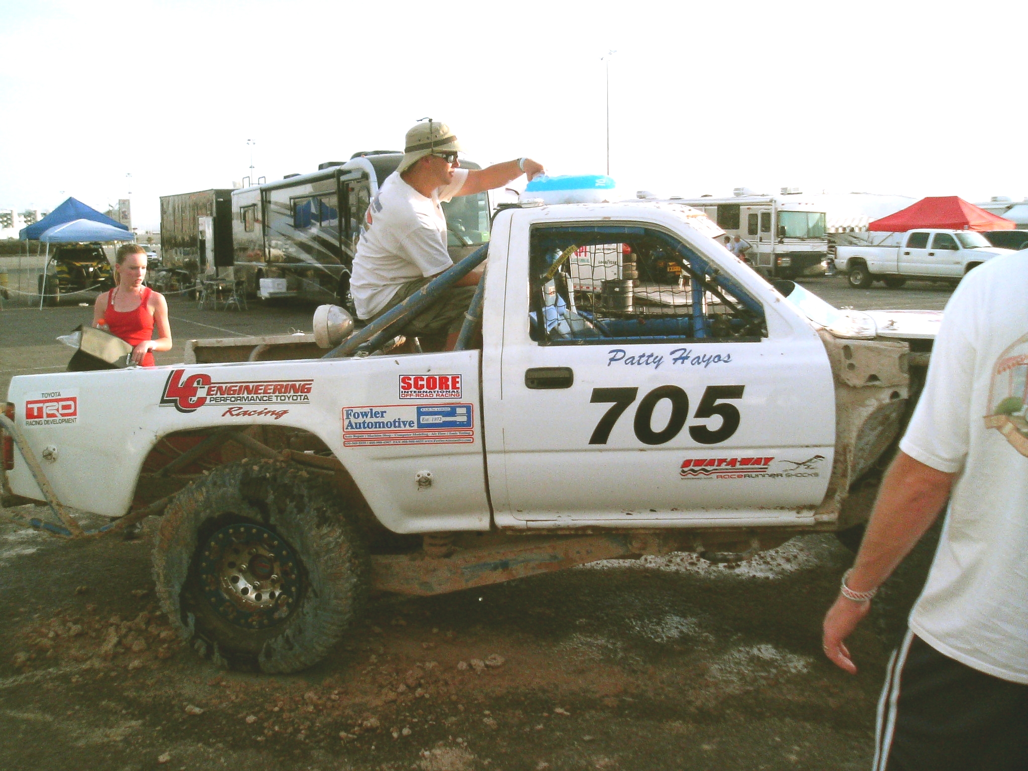
She has recovered and the truck is being rebuilt for the 2008 season.
Part of that effort is overhauling the 5V-FE engine again because it sustained minor damage from running upside down. That was done in my shop and installation was done at the Hayos Racing facility. It is presently being run for testing and practice on a track in the Prairie City Off Road Park in central California. Several additional Toyota engines have been obtained for modification and development at Fowler Automotive because this platform has a lot of room to make more power. At least two more chassis are being built by the Hayos team and the teams future looks promising.
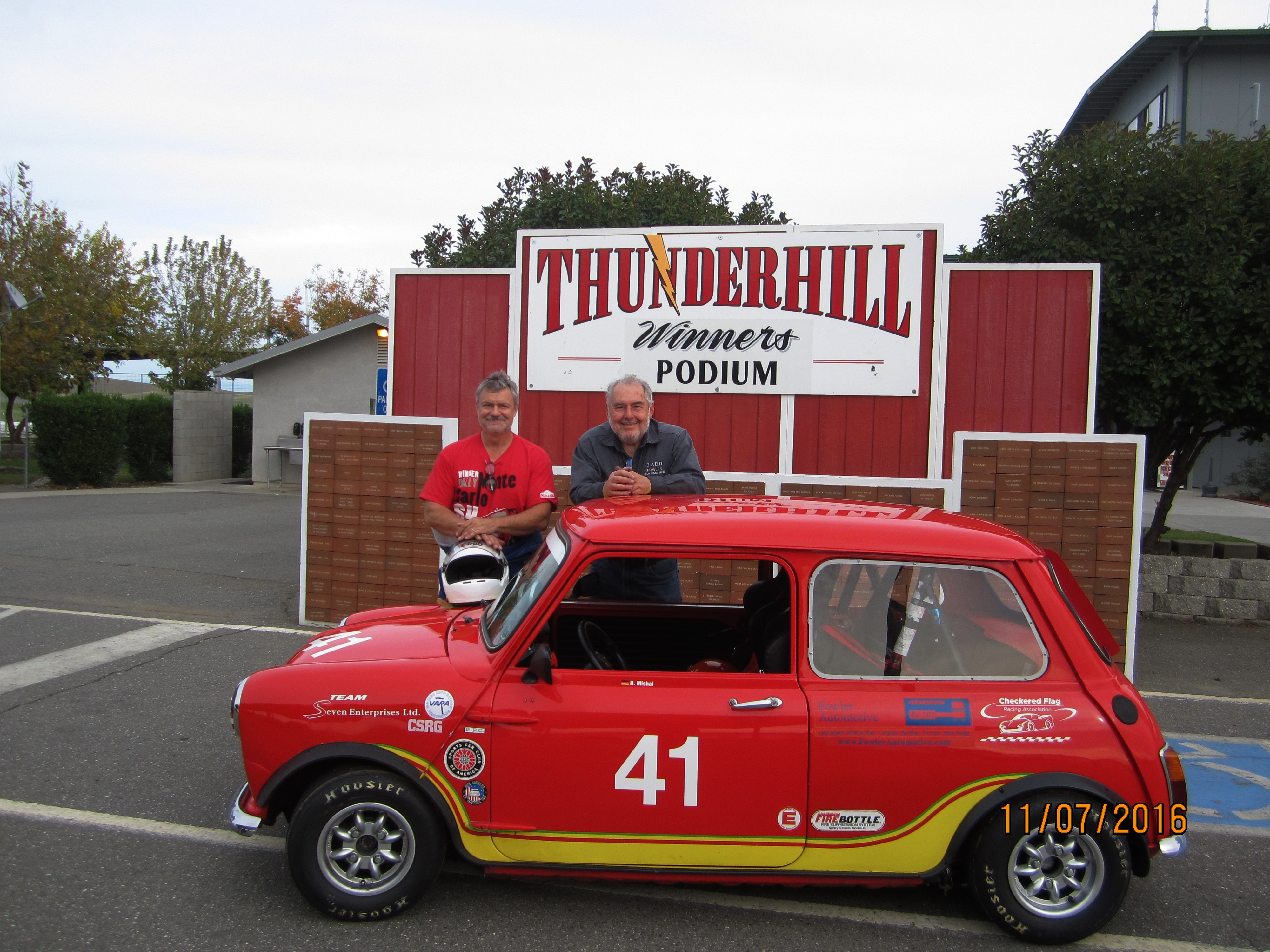
Vintage Mini Cooper race car & Ladd Fowler engine and car builder biographic sketch
Greg Jones
Managing Editor, Engine Builder<http://www.enginebuildermag.com/>
gjones@babcox.com<mailto:gjones@babcox.com>
(330) 670-1234 x272
3550 Embassy Parkway
Akron, OH 44333
Good
evening Greg, I’ll put my response
to your questions in blue. I’ve metaphorically
tossed you a majority of
whole baby’s story, including its blanket and buggy. Ladd
* Can you give me some background
information
about
yourself? How did you get into the industry/engine building?
I’ve
been a mechanic since I was
very young, 7-8 years old. Back then my dad gave me a go kart fitted
for a
Briggs & Stratton lawn mower engine which I had to swap on and off
his
mover to ride the kart. I always had access to his hand tools to make
things and
a few years later when I was 12 he gave me a set of welding torches.
That led
real fast to building two stroke mini bikes running McCulloch engines
which
were flat out dangerous – I’d chase down DT1 Yamaha
motorcycles in the Santa
Cruz Mountains pretty successfully. I’d heard a story that the
mark of a true
master mechanic was being able to do things blindfolded so I taught
myself how
to build the McCulloch 91 – 101 engines blindfolded when I was a
freshman in
High School. I also rebuilt every one of our family car engines with my
Dad –
Buicks and Cadillacs - between late grade school to college years.
By
then my older buddies and I
had motorcycles and cars which we worked on after school when we
didn’t have
jobs to attend to. By the end of my junior year I was maintaining a
dairy
processing plant three days a week because I was nearly the only one at
that
business who (intuitively) understood their pasteurizing and bottling
equipment. Eventually I became one of the youngest licensed processing
plant
operators in the state, getting my license at age 18 under the tutelage
of a
state inspector. And a few afternoons a week I worked for a lumber and
supply
company fixing trucks. I was also fixing
cars for people who somehow found out I could do that when I was not
working
elsewhere.
This
gave me a chance to know
our local auto parts supplier well. They had a machine shop in back of
the
store which fascinated me because I had constant need for industrial
and
automotive parts and machine made or repaired pieces. Somehow I
graduated High
School as a “C” student. Looking back that is amazing
because I never did any
homework or read assignments. I also missed many classes when called in
to work
early.
In
my
senior year one of my
buddies had a neighbor who was racing Mini Cooper “S” cars
and Corvettes in
SCCA autocross events with some success. He bought a Mini Cooper to
repair to
be like his neighbor. Occasionally I helped my buddy convert it to
“S”
specification by swapping performance parts into it. Because I was the
guy who
had a torch set we used that to heat-then-beat his firewall in for
carburetor
clearance. It was the first car I ever caught on fire. We put most of
the fire
out pretty quickly, but it continued smoldering for hours under the
dashboard.
I
had
bought a ’65 Pontiac GTO
by then because my mother forbid me to buy a Corvette saying they were
too
dangerous. Looking back that was actually a pretty funny turning point.
The GTO
didn’t stop, couldn’t turn, and had more power than many
Corvettes. It was the
more dangerous car which shortcomings I initially proceeded to amplify,
not understanding
even more power would make it handle worse faster. Some other friends
were autocrossing
a Boss 302 Mustang with OEM support, various Corvettes, and Z-28
Camaros so I
tagged along with my GTO. I believe I was 7th in the county
one year
running in the SCCA “H production modified” class, about a
second behind the
Camaros and 2 seconds behind the Corvettes. I was rebuilding my
Pontiac’s
engine almost monthly because I couldn’t get good timing chains.
And I didn’t
understand valve train geometry that changed because of various
cylinder head
swaps until a bit later on. When Cloyes came out with double roller
chain models
and some hot rod magazine did an article about checking valve to rocker
arm
contact points my engines started to run better and longer. I also
began to
learn about chassis set up trying to make that GTO corner like a
Corvette.
But
my
buddy and I drifted apart
after High School so I didn’t work on a Mini Cooper again until a
couple of
years ago. I mostly worked with other
vehicles, some of which became known as “muscle cars”, and
repairing machinery
and equipment.
In
1972 I started what eventually
became my small automotive repair business. And I continued to seek out
opportunities to gain further education to validate what I was
attempting to
do.
I
attended Foothill College majoring
in business administration but that was very hard for me. The scale of
business
size discussed in class started with a few hundred employees but I
wanted to
learn about proprietorships and partnerships with a few guys. After two
years
of agony I switched to De Anza College majoring in their auto
technology
program, then graduated 2nd in my class. At graduation I was recruited
by the
auto parts store I was doing business with to be a machinist in their 3
man back
room shop. After a year the business owner opened a second location and
I was
offered that stores machine shop as a solo gig. But
I quit on good terms despite my love for
machining to go east for what became an office job running finances and
managing a fleet of 65 cars scattered throughout the New England
States. After
a couple of years of freezing winters and shocking eye opening
experiences with
rusted out near new cars I came back to sunny California to more
formally open
“Fowler Automotive” in 1976. It was an easy economic
decision despite being
asked to return to work by business owners of every job I’d ever
held. I could
make in a day in my own shop what took a week to earn as an employee.
So I
serviced those businesses as an independent contractor while gaining a
few more
dedicated clients whose families I served, in some cases, for three
generations
before I retired a couple of years ago.
* Can you give me some background about Fowler Automotive? When did it
start?
What does the shop specialize in? Do you work on an assortment of
engines and
applications? Is it a full machine shop? Do you do everything in-house?
Fowler
Automotive has been a
sole proprietorship since 1977. It was formed as a home based service
business
with a somewhat backwards business plan. I have done a very broad
variety of
automotive and equipment related services for a small select client
group for
the last forty-five years. For their various needs and interests
I’ve cared for
everything from small rototillers to long haul diesel trucks with a few
boats,
motorhomes, and an airplane tossed in. Some of that work was strictly
economic
business - to get something working again so it could generate profits.
Some
has been recreational to enable their various trips, movie shoots, or
competition / restoration projects. And a majority of it was in-between
those
categories where I was providing ordinary repair service for their
family
vehicles. Over those years I accumulated equipment and tools to meet
their
needs as I went along.
Along
that path I’ve been
invited to and attended GM school, Ford Industrial Engine School and
countless
clinics or manufactures training sessions. I sought out an opportunity
to
attend Cummins Engine School. I went back to college at night to
formally learn
welding skills and non-destructive testing processes.
I
was
lucky to trade Joe
Mondello an intake manifold resurfacing fixture I invented then
patented for
attendance at his engine and head porting schools. Bill Jones of
Taylorsville
Utah took time from his life to teach me a lot about head porting and
air flow
from a practical perspective. I’ve been tutored by Allan Lockheed
and Dema
Elgin in advanced engine design and competition engine preparation over
many
years’ time. I’ve had significant passing acquaintance with
several really
great leaders in fields of business ethics and industry procedures who
mentored
me as I helped them. I was among the first technicians to be tested and
awarded
ASE “Master Mechanic” and “Master Machinist”
certificates. I kept both those
ratings current until a couple of years ago. Becoming and staying
educated in
my industry is central to the success I’ve had meeting a diverse
range of
client requirements.
In
the
1980’s I was doing a lot
of Corvette repair and service as Fowler Automotive in conjunction with
another
friend’s business; Herlinger Corvette Repair. I also ran an entry
level stock
car under NASCAR rules in the Winston West series. I did well as an
owner /
rooky driver finishing tenth place out of over 250 cars registered to
run in
the area. But I didn’t have time to build my own engines despite
having
education and training to do that. So I hired it out. When my engine
builder
became ill with cancer I bought his home and automotive machine shop to
enable
continuing service for my clients, and then helped care for him until
his
passing. After his passing I sold my stock car then sponsored out of
that
machine shop, over the next twenty years in small ways, TrueSpec Racing
who ran
Chevrolet engines in various dirt track venues, Pennington #9 Racing
who ran Ford
Clevor engines in IMCA modified events, and Hayos Motorsports, an off
road
truck team running Toyota engines.
I
have
used a simple rule of
thumb for business equipment acquisition. If it will pay for itself in
a few
jobs I’ll acquire it or establish a working relationship to use
it. I have come
to understand a business principal – you don’t need to own
everything for a
“full shop” but you do need to have knowledge of where and
how all those
machines work and how to gain essentially immediate access to them when
needed.
A growing problem which now confronts service providers like me is many
of our
vendors and affiliated shops are closing so their inventory and
equipment
disappears which makes it far harder to actually create new automotive
race
cars, hot rods, or restore vintage vehicles.
A
bit
more than a decade ago I
was diagnosed with leukemia and have been in and out of experimental
chemotherapy since. A few years ago my automotive vehicle / fabrication
shop
was zoned out of existence after being in that location for more than
35 years.
But I was able to keep my automotive machine shop which was in the next
town, mostly
for hobby shop interests. I still own a lot of metal fabrication
equipment and
traditional industrial machine tools, most of which have gone into
“semi-storage”
circumstances.
As
Fowler Automotive I have been
“the kid” in a circle of older car guys who owned
businesses I ran with. Many
of whom were far more talented than I. Many of them have passed on. I
am now
semi-retired and specialize in doing fun things with my remaining
clients, who
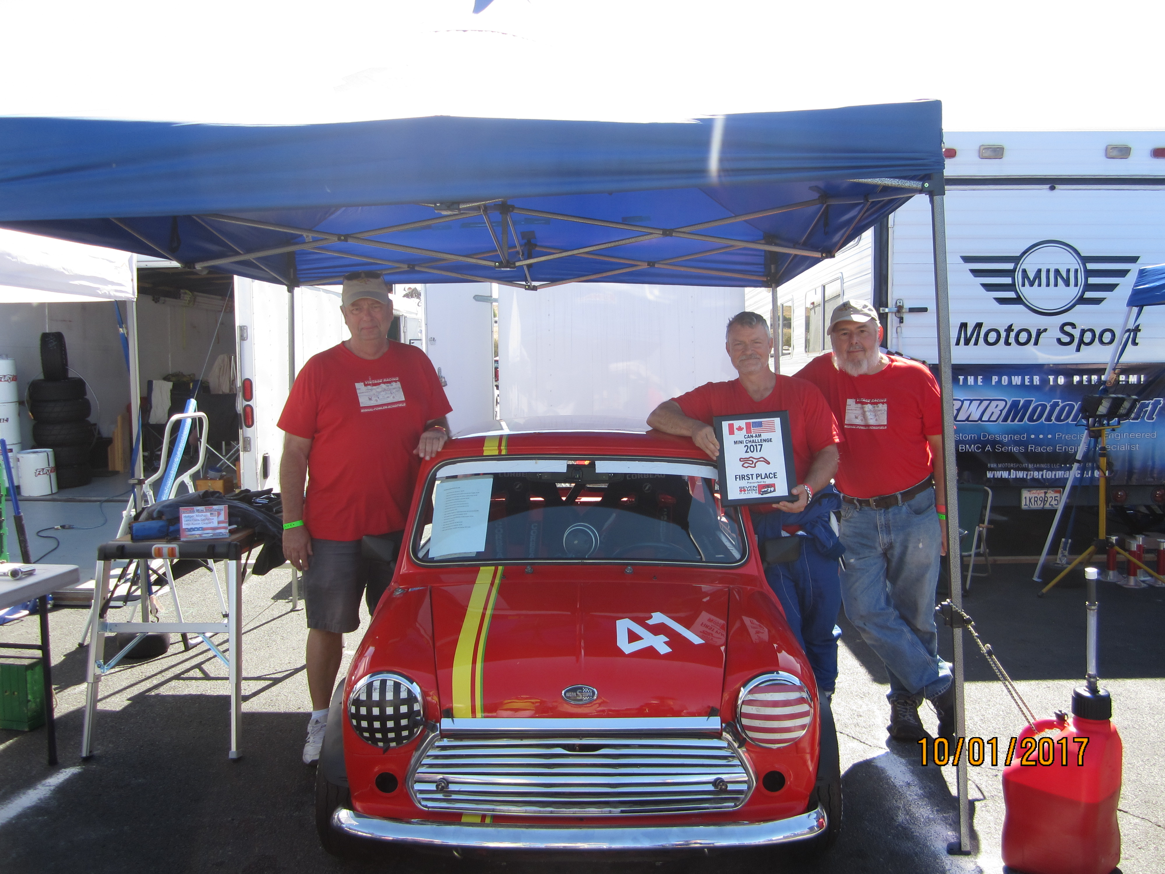
have become friends and buddies. We do projects; like building this
Mini Cooper
to win the Nationals. For us, fun projects seem to attract more fun
projects so
we are considering getting another building, to both gather our
collective
equipment into one place and consolidate more of our labor into one
spot. But
the financial implications of doing that in the Silicon Valley simply
don’t
make sense. So we may fade away like so many other shops have done.
* Layand Engine – How did the engine get to the shop, is this
from a repeat
customer or new customer?
This British Leyland engine came into
my shop from a
client I’d built a 1966 Mustang for. His wife wanted a V-8
automatic
transmission light blue with white interior Pony Pack convertible. I
built them
one from a brown on brown car that sat oddly and too high, which turned
out to
be full of hidden body damage. I saved the front clip, cowl, floors,
and trunk
lid to build them a car from that, in cooperation with a body shop.
When he
wanted to go racing he bought a Mini Cooper to relive and extend his
college
experiences driving that marque from days when they were new. Because
he was so
pleased how that Mustang turned out I was invited to straighten out the
Mini
Cooper after he had some bad experiences in other specialty shops.
* What was wrong with the engine/reason it was there?
This
Mini Cooper was a beautiful
show car semi-converted to be an autocross play car. After being
purchased by
my client we took it to Thunderhill Race Track in Northern California
for an
open track test day with other clients of mine who were running their
cars. It
drove ok and showed promise of becoming really fun. It was the first
Mini I
ever drove. He decided to send his Mini to two nationally prominent
Mini Cooper
shops for “road race” preparation and various upgrades.
Then
the car owner took it to
Sonoma Raceway for an event after spending many thousands of dollars
where he
experienced multiple significant vehicle failures. He called me to the
track so
I could trouble shoot his vehicle where I found issues with ignition,
carburetion, charging, cooling, and engine valve train interference.
There were
also fluid leaks, and generally poor assembly which taken all together
prevented his Mini Cooper from making an entire lap under its own
power.
I
fixed what I could in the Pits
with generous help from other racers in his class – remember;
I’d not worked on
a Mini Cooper since high school – almost 50 years previous
– so I had to take a
moment with a knee on the ground with it, so to speak, then another
moment to get
my brain to see what my eyes were looking at. I was able to get his car
to run
a couple of places in front of being last by the end of his event
program.
The
car was returned to the
building shops for “warranty service” where it was fitted
with a new transmission,
more engine upgrades, swapped its Weber carburetion set up for
SU’s, received
an alternator, and so on. He felt confused by this, especially when it
broke
the new transmission on his next outing vs. the turnaround he had seen
under my
care. So I was hired to fix the car and act as crew chief for his next
season,
after it was again returned to the other shops for a replacement
transmission.
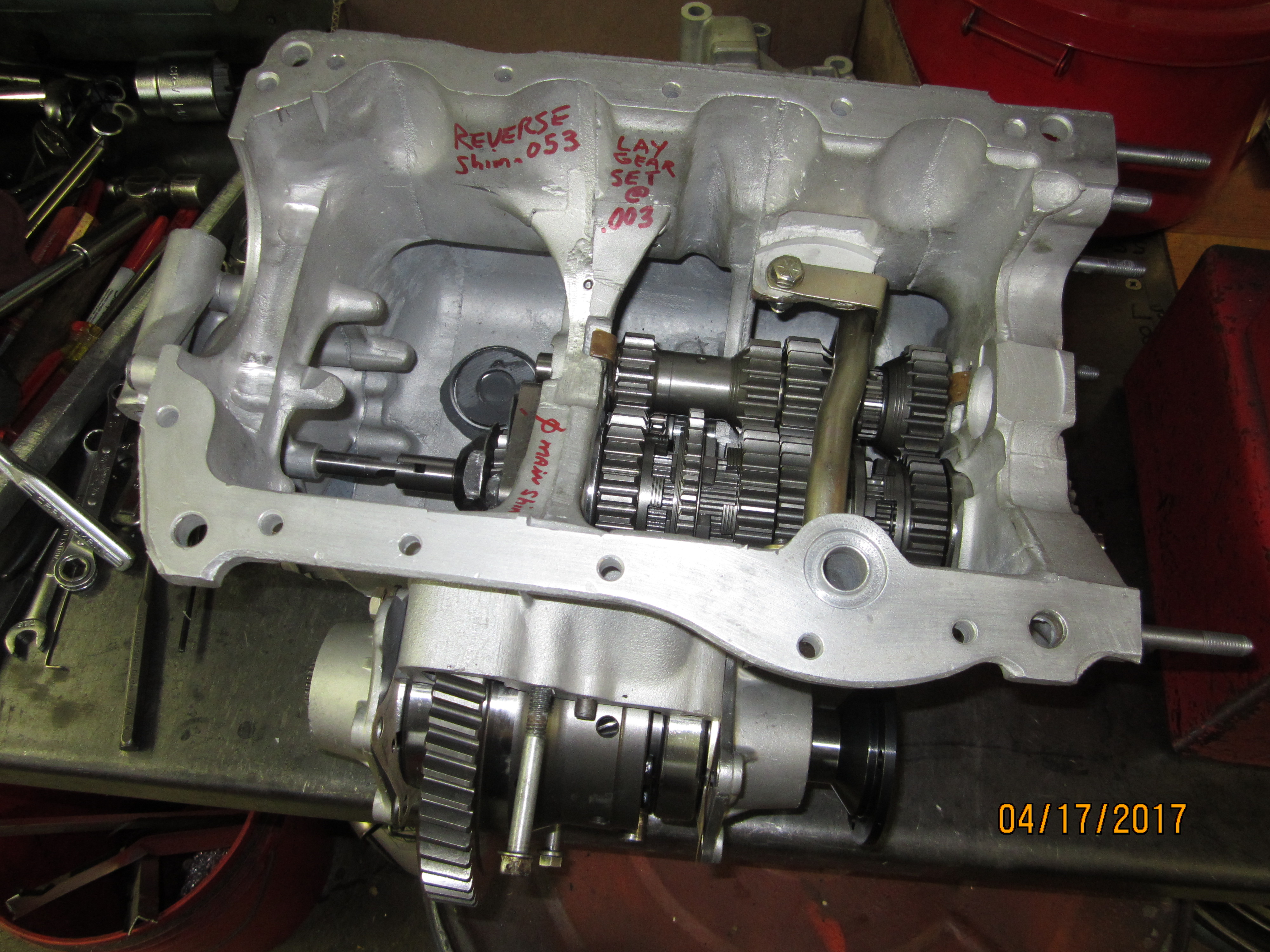
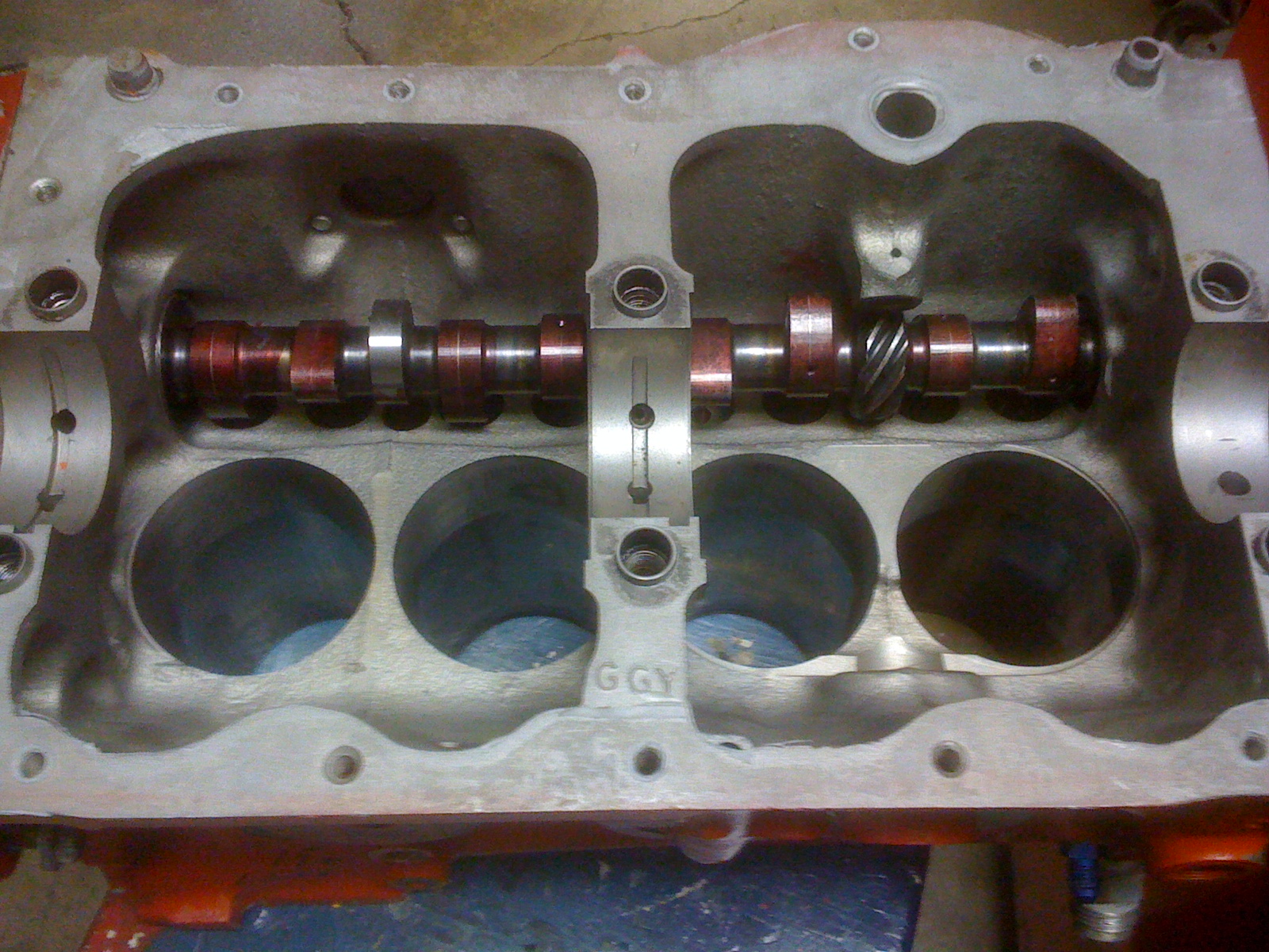
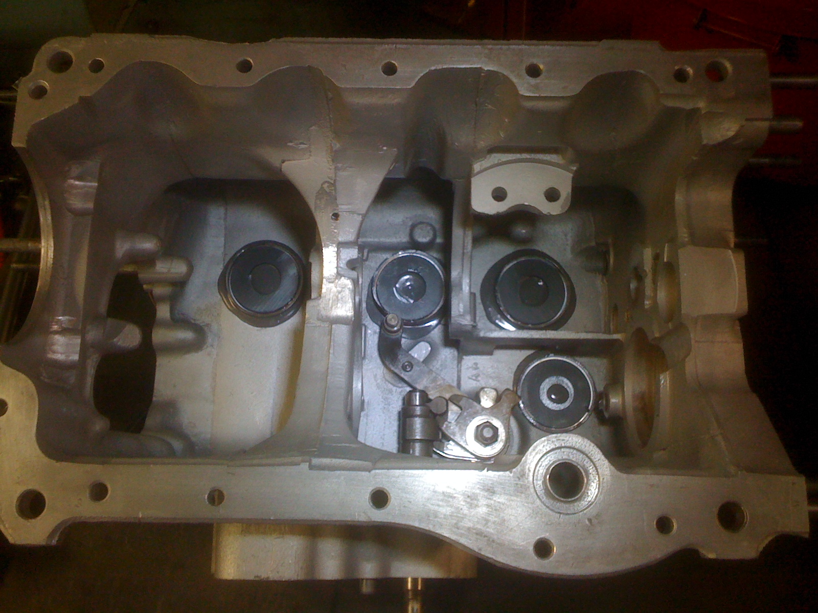
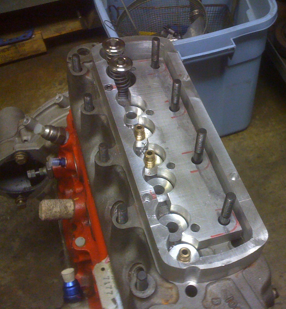
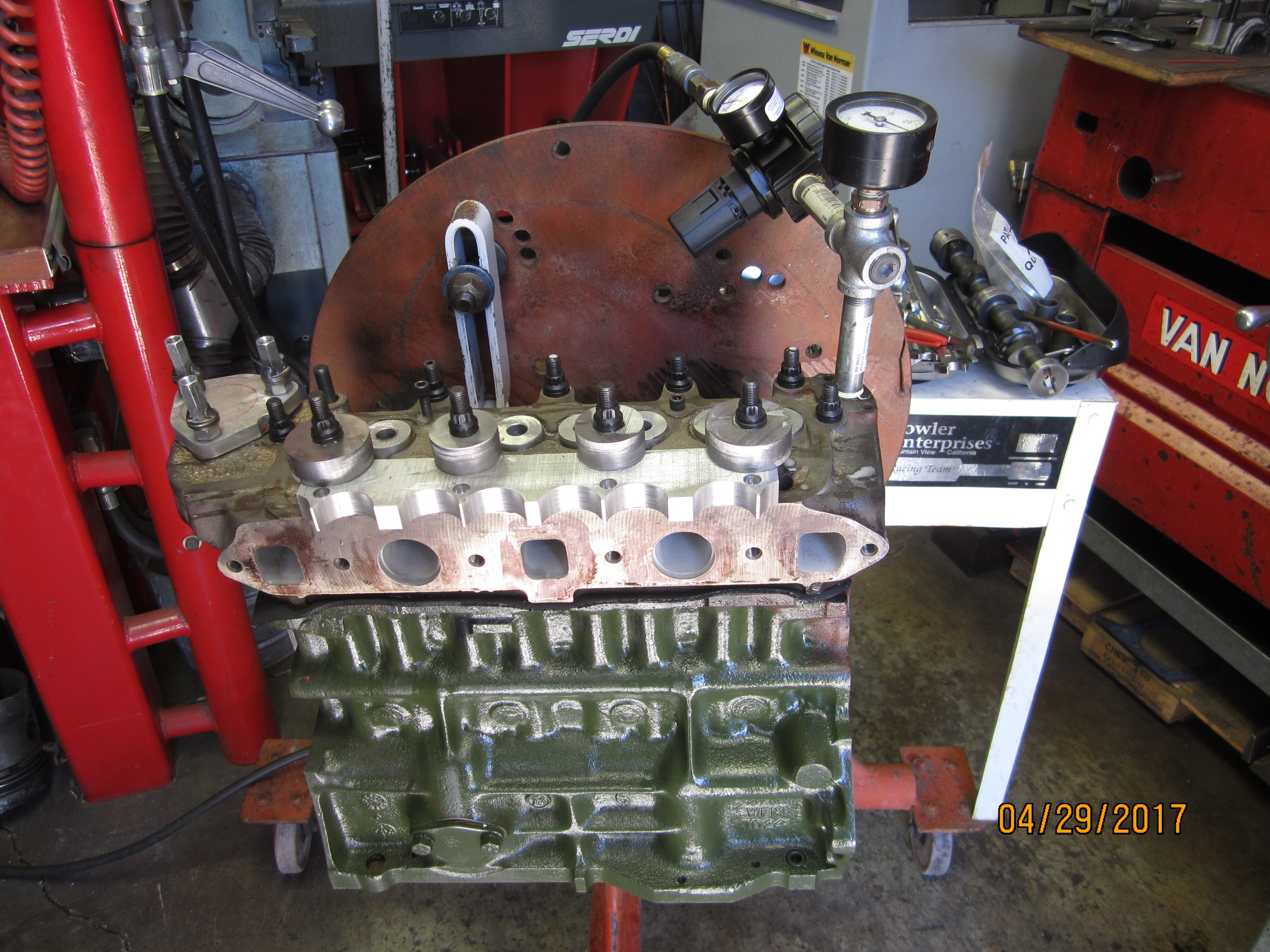
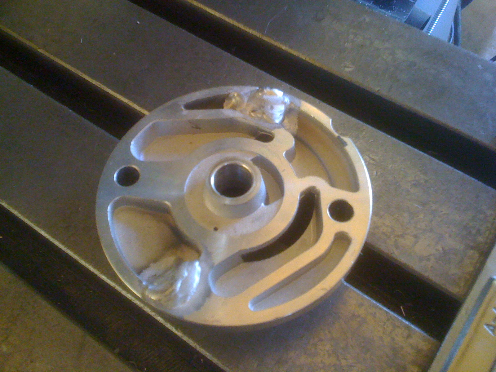
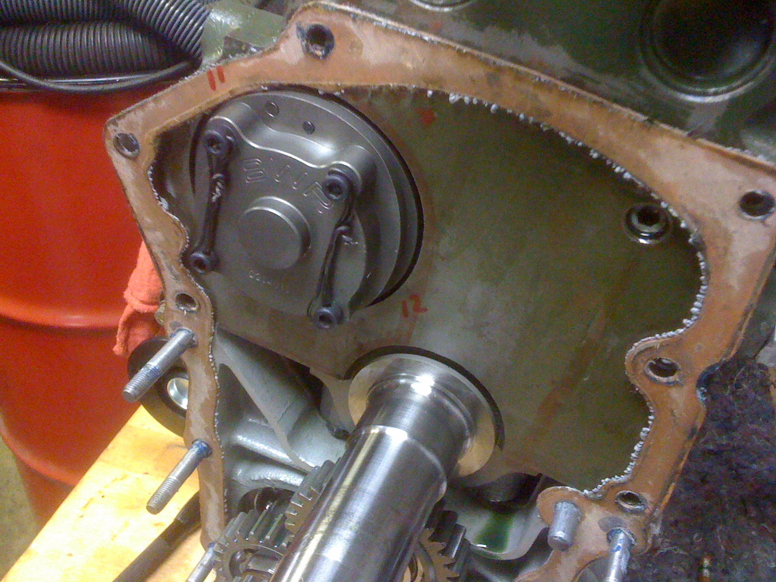
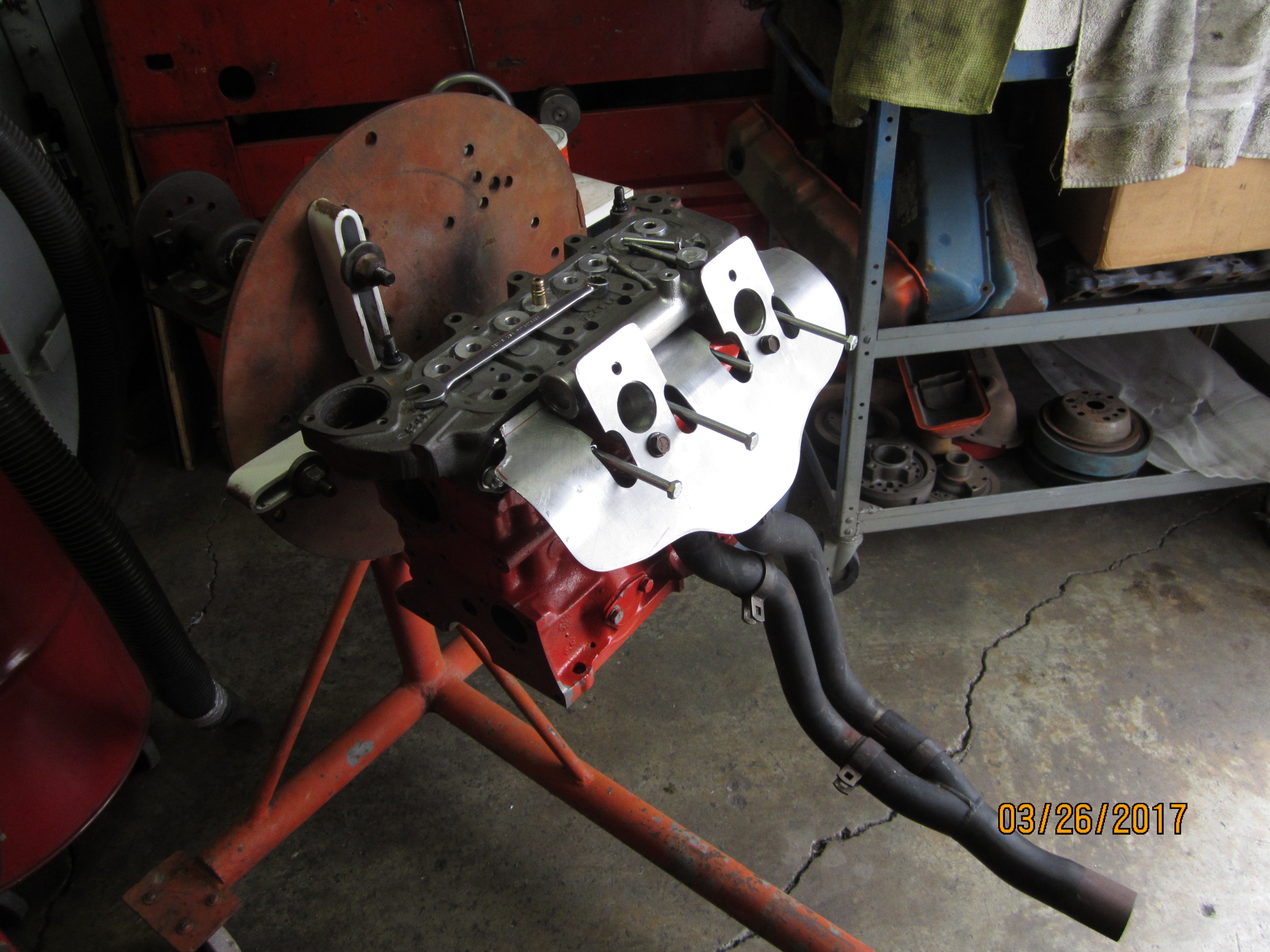
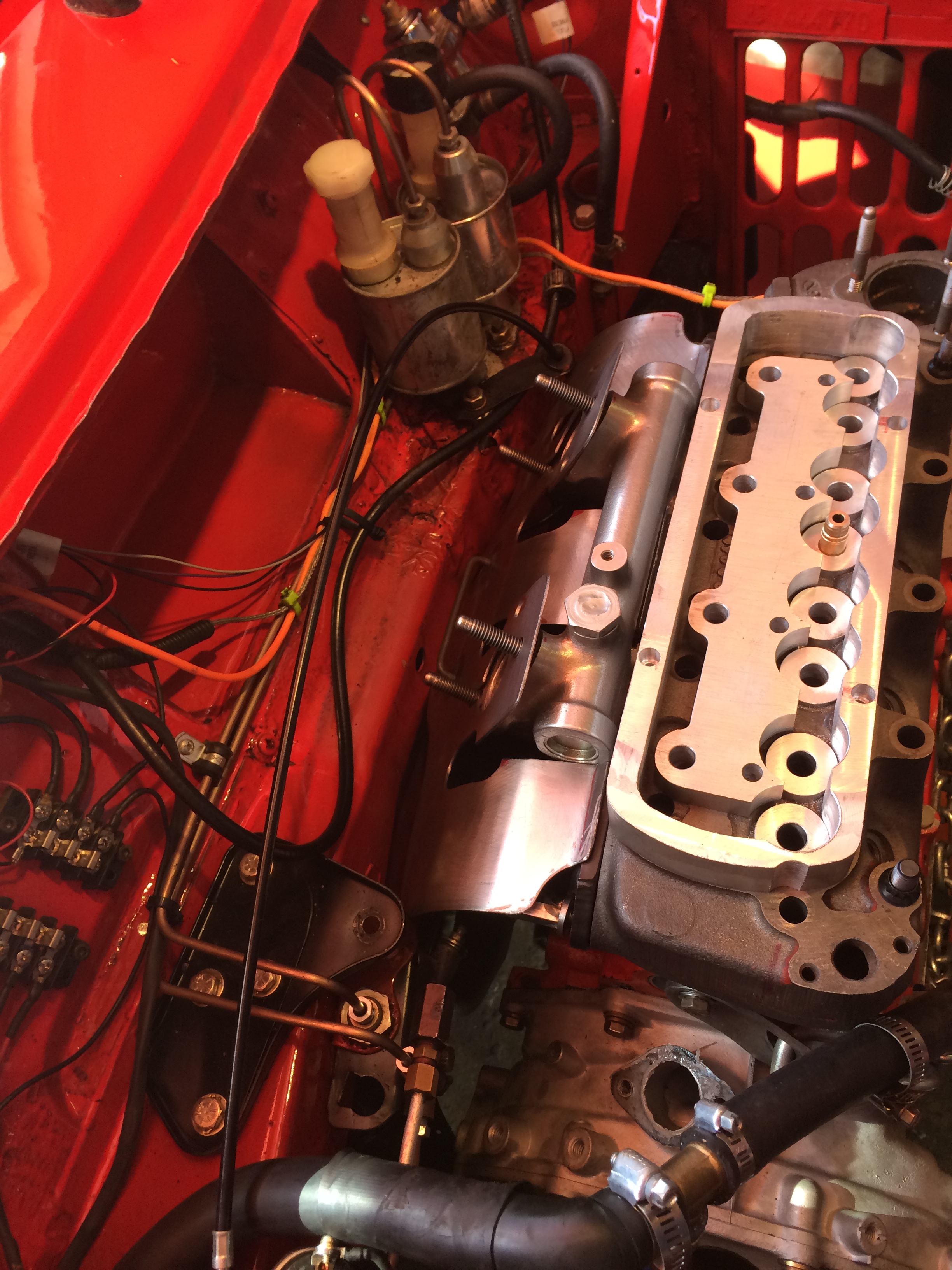
Because
the Mini Cooper engine
crankcase also houses the transmission and differential while sharing a
common
oil system it is very hard to talk about just the engine, because, if
some part
of that system fails it usually wipes out everything else too. Pictured is my client’s crankcase assembly
ready to receive his modified race engine.
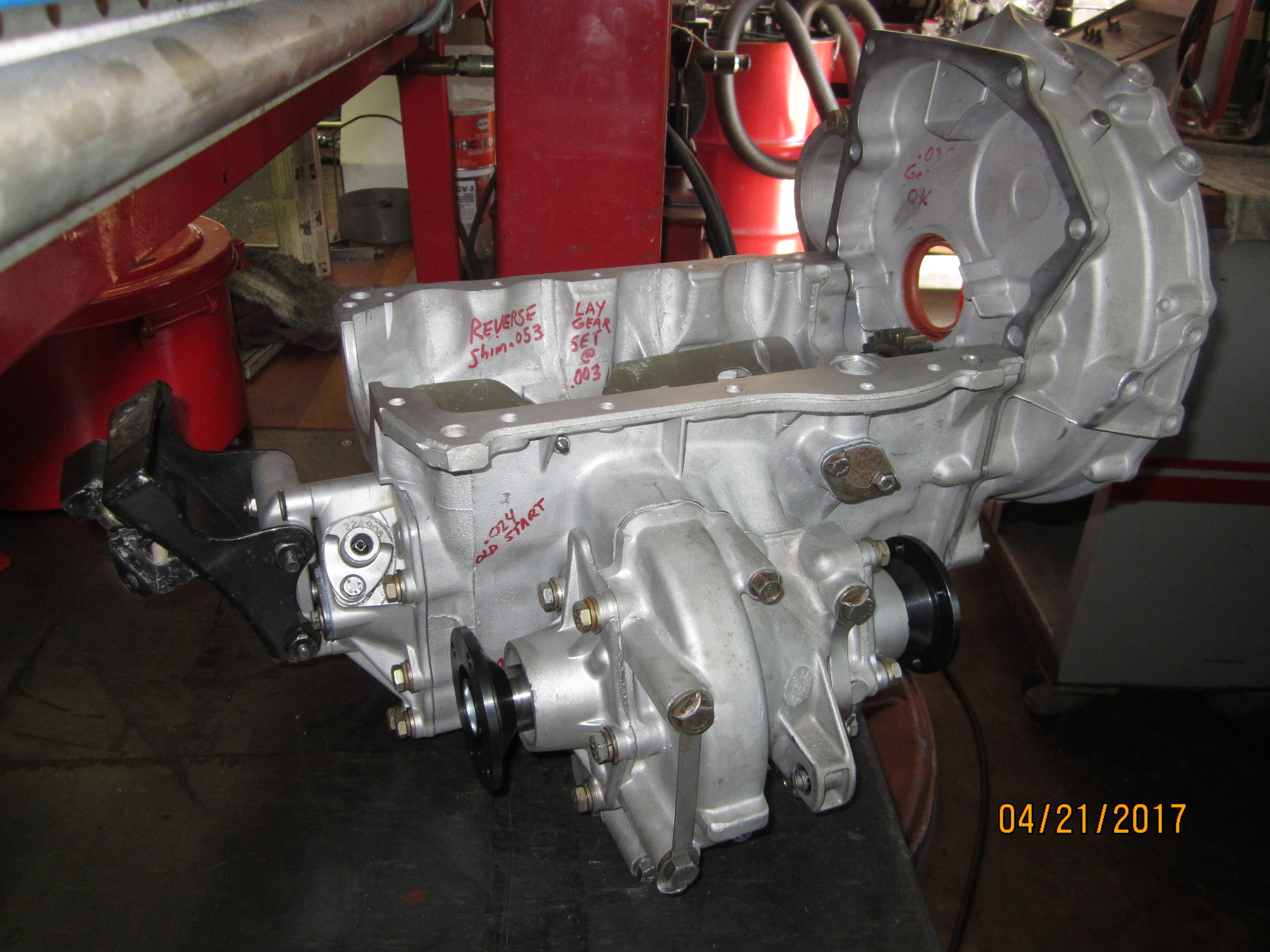
Because
the Mini Cooper
driveline is so short and suspension so closely coupled, any suspension
or
driveline vibration or failure can affect the final drive inside the
engine
crankcase, which can then damage the engine.
* What application is the engine for? Does the Mini Cooper get raced,
or was
this just for a restoration project?
This
Mini Cooper project started
out as a vintage road race effort on a “hobby” basis. After
a couple of events
I had his car running mid pack, about 6 seconds off the leaders at
Sonoma and
Laguna Seca tracks.
This
is a dangerous position to
be in because other cars can hit you when you are in the middle of
things. We
were discussing improvements to his car which would allow it to move
into
running with more capable cars and drivers when he was lightly kissed
by
another car whose driver turned right in a left hand corner rubbing our
Mini
Cooper in its left rear fender arch. Our damage was near zero, 10
seconds with
buffing wax took the rub mark off and a washer under the screw head of
the Mini’s
plastic wheel arch molding fixed that. However, in my opinion, the
driver who
caused contact between the cars complained so effectively about
“over
aggressive driving” he got my client and himself suspended for a
year. We were
shocked at the ruling, but within a couple of months figured we’d
use that time
to rebuild the Mini Cooper correcting fundamental issues and making
upgrades.
It was a turning point away from “restoration” towards
“race car”.
* What kind of work did you have to do on the engine? Machine work to
the block
or other parts? Other adjustments, etc.?
To
gain 6 seconds lap time vs.
the leaders we deliberately analyzed options open to us within class
rules and
known parts we could buy. Modifications were planned by study of
“A+” series
engine existing art and published articles, then by my client’s
sense as a
driver of what he needed to go faster. The engine rules for our vintage
class
dictated a non-roller rocker arm assembly be used and
visually period correct appearance of the
engine. We had to use SU carburetors and could not modify the engine
compartment sheet metal (for more velocity stack clearance) past what
was done
on original “S” model vehicles.
In
this case engine work started
with another transmission gear set which had dog gear shifting pawls.
We
calculated a 2 second per lap gain was likely because of quicker
shifting speed
and having better ratio selections. We also felt replacement of the
differential with a Quaff torque biasing unit would extend engine and
tire
life. Conventional traction lock and posi-traction clutching
differentials shed
materials into their oil supply, which in this engine are then fed into
the
engine bearings. We had excessive wheel spin in corners that was
melting our
tires which we felt could be better controlled.
Opening
the crankcase for gear
replacement would lead to inspection of the engine’s condition,
which had
excessive pressure indicating poor ring sealing.
Replacement
of the gear sets
would also allow replacement of both axle assemblies with lighter,
stronger,
smoother running shafts thereby increasing power available to the
wheels, and
reliability. In my opinion running stock Mini Cooper drive shafts above
90 mph
is insane. A broken driveshaft might strike the oil sump knocking a
hole which
will cause engine failure, a fire, and perhaps a wreck. Our Mini needed
to exceed
110 mph to win; therefore we needed upgraded drive shafts.
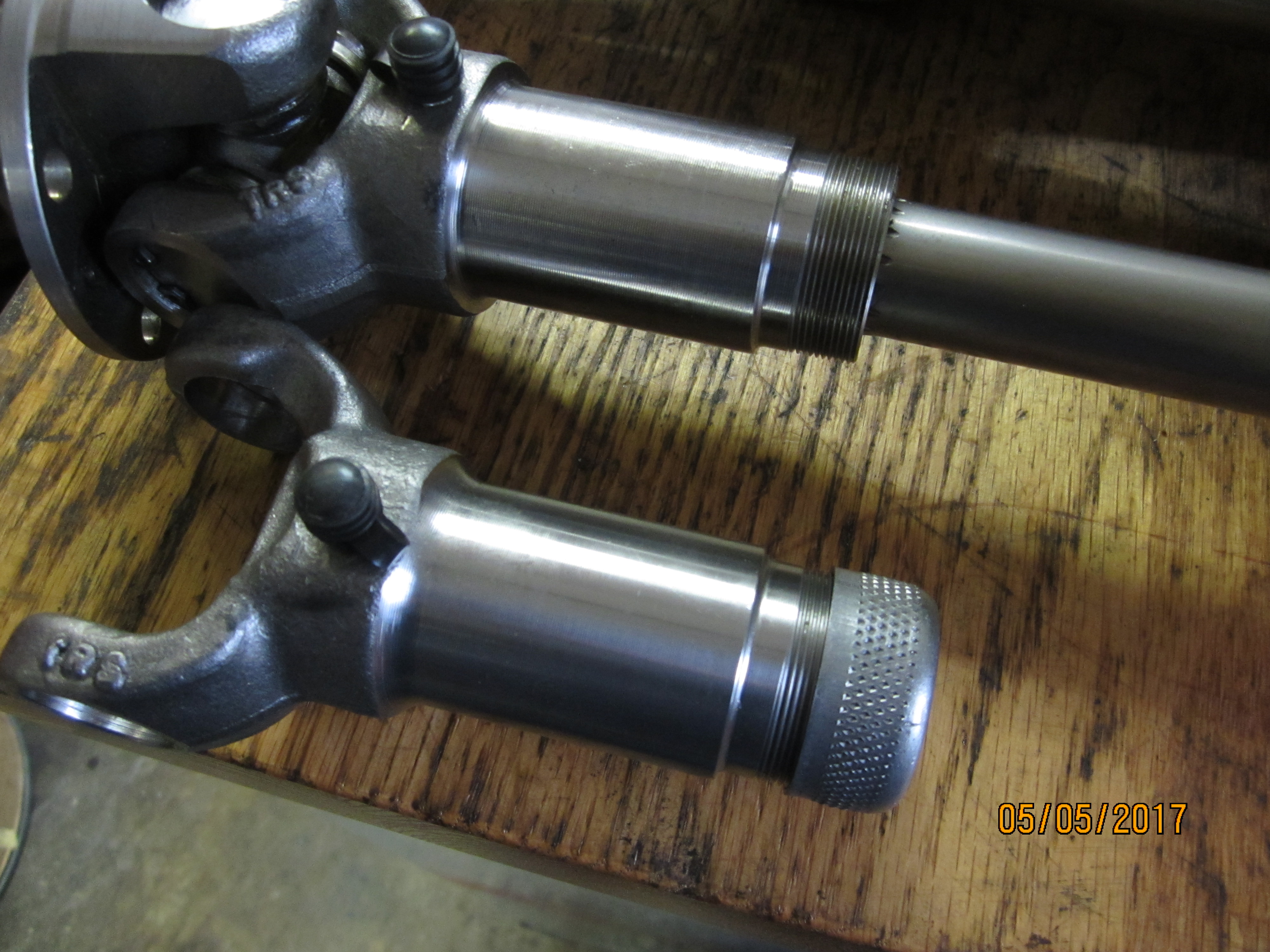
Swiftune
provided 10 spline
Hardy joints from Spicer with shafts and yokes to match. But they were
not
shipped with a grease seal and packing nut despite having a grease
nipple for
lubrication. If installed as shipped they would toss grease directly
onto the
headers causing a fire hazard. Swiftune, when called, said
“nobody runs the
grease seal or nut so we don’t send them out that way”. And
then said they
could not supply them. Our local Spicer dealer could sell us new
(identical)
yokes with the seal and nut preinstalled so we bought them, robbed
their seals
onto the Swiftune parts, and saved the extra forged sections for spare
parts.
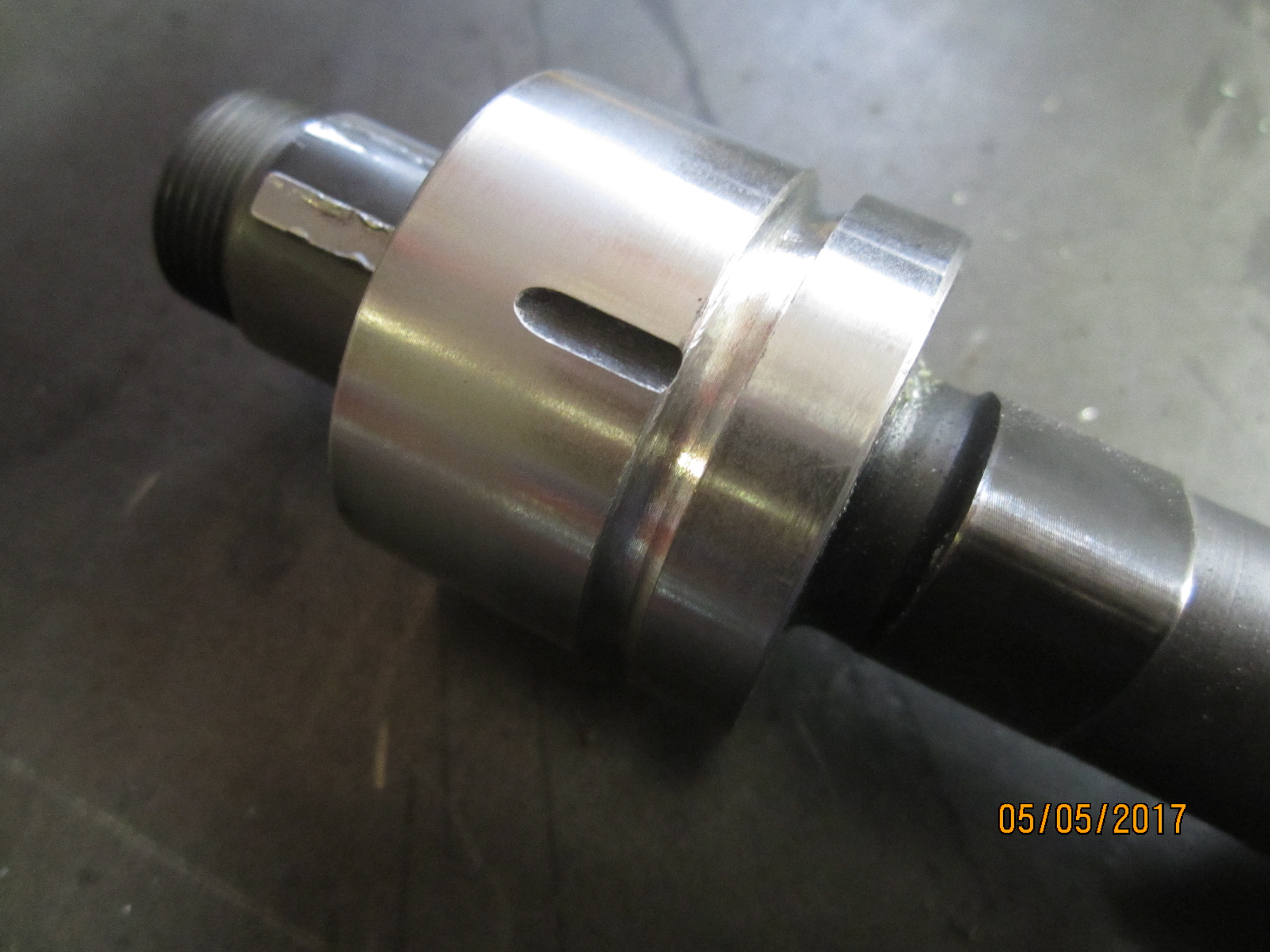
There
was a second minor issue
with Swiftune supplied output flanges. The Quaff differential, on the
RH side,
would not allow its flange to seat fully into the differential where a
snap
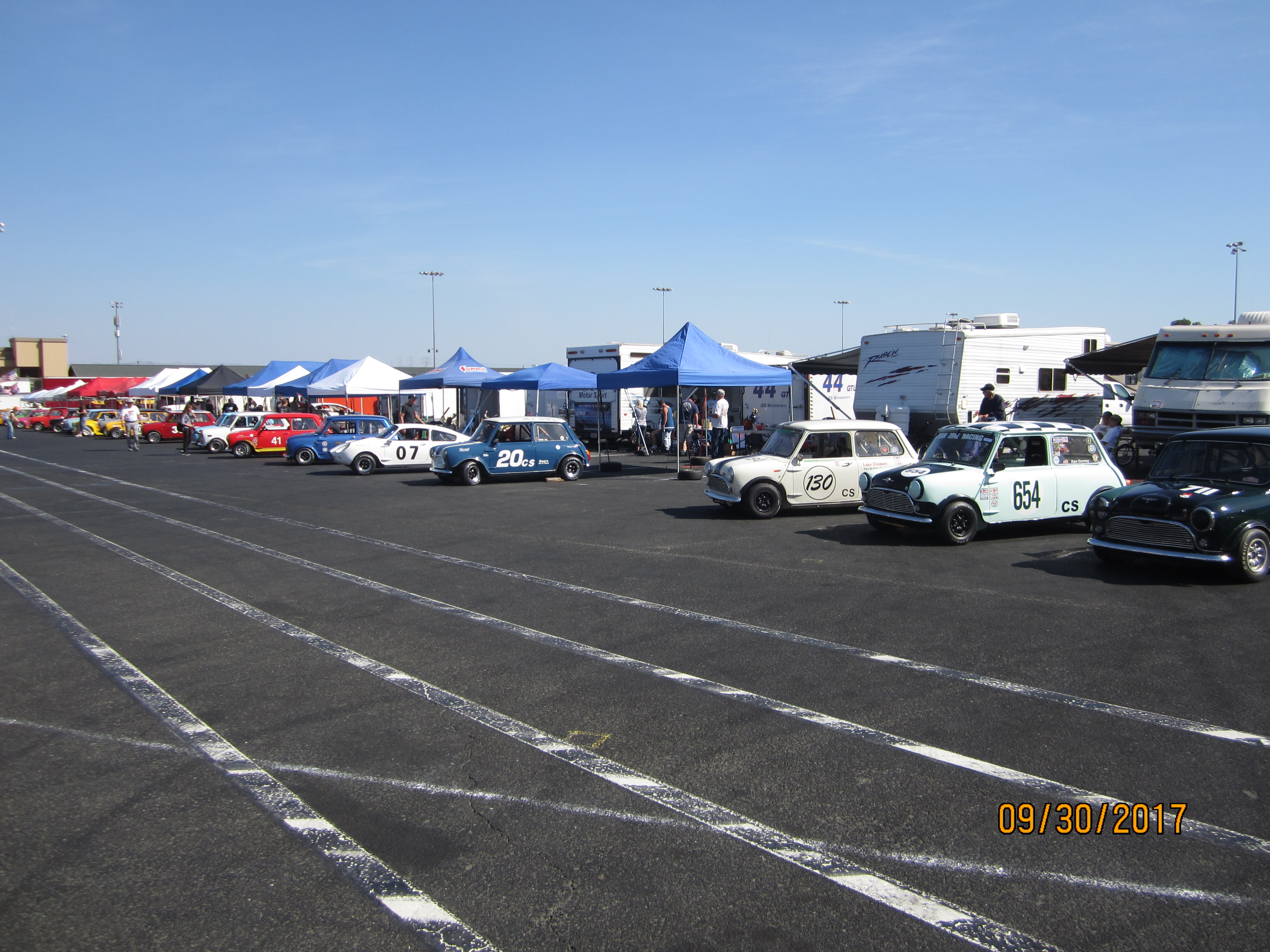
ring would retain it. This was not discovered until the car was pitted
after
qualifying laps in the 2017 Canadian / American Challenge race weekend.
The
yoke had walked out of the case introducing a vibration into the
driveline. A
quick trackside fix was to put a hose clamp on the axle which retained
the
yoke. A permanent solution done later on was to machine about .075 off
the yoke
which allowed it to seat fully.
To
gain more seconds on leading
cars my client’s engine would have to rev higher. Virtually all
Mini Coopers
that road race in various divisions of vintage stock class use one size
of
Hoosier tire. It is the only one available. To gain top speed, and
because
final drive ratios are essentially limited to the one you build an
engine with,
the engine itself needed modification to run faster. Virtually all
historical
wisdom, and both professional Mini building shops in our area indicated
limiting RPM to under 6500 - 7000 would delay crankshaft failure for a
season
or more vs. failure within a couple of events if run faster. To run
“up front”
we needed to increase engine speed above 8000 RPM which meant
engineering for
9000 RPM to create some safety for over-speeding incidents. To gain
that
increase in engine speed virtually every part of the engine needed
modification, including the induction and exhaust systems.
* What parts did you use in the engine?
Please let me know
the specific part and manufacturer – block, cylinder heads, rods,
pistons,
crank, camshaft, bearings, gaskets, valve train, etc. Do you prefer a
certain brand
of oil?
Despite
having a new OEM
crankshaft in an “A+” series block running new upgraded
rods and pistons we
retired those parts in favor of a dedicated DC5-2 racing lightweight
rotating
assembly from Swiftune in Europe. They recommend against using a
harmonic
damper, which in my opinion is utter foolishness. We used a Fortech
FOR098
racing damper. We also bought Swiftune’s “Feather
Light” lightweight clutch,
upgraded drop gears, pistons, bearings, double row timing chain, and
electronic
distributor assemblies. I believe they also marketed the dog gear
transmission
kit and differential by Quaff. We had a “Longman” C-AHT221
cylinder head, fully
worked to current racing configuration, but determined we needed to
retire it
also, in favor of one ported a bit differently. I made a new head based
off
casting #12G940. We bought a Swiftune camshaft and tappet set with cam
bearings
to suit our intended road racing use. Virtually all smaller parts like
thrust
washers, fasteners, and gaskets came from Mini Mania and Seven Mini
Parts. All
three companies, as vendors, are quite good at having everything needed
in
stock for immediate shipment.
Computer modeling software from Rapid Line and
Performance Trends was used to influence many aspects of our decision
making.
I’ve used both programs for many years and upgraded both for this
project to
their newest “Pro” versions.
I
made
an informal poll of most
Mini Cooper owners at a couple of events we attended in 2016 regarding
engine
oil. Most teams were running Redline 50w synthetic oil without any
problems at
between 75 to 90 psi. At that time we were also, which I felt was an
area for
some testing and possible improvement.
* Did you hit any road blocks with this build, or did it go together
fairly smoothly?
Our
troubles started with this
build almost immediately. Nearly every engine part and subassembly
needed rework
help except the actual crankshaft and rods. By contrast the
transmission and
final drive kits were straight forward and nearly flawless. In the
transmission
only reverse gear needed a small bit of “grinding love”
with an abrasive wheel and
a couple of thin shims to assure clean disengagement.
Beginning
with the premise of
“trust nothing and nobody” I sent the Swiftune #SW2307
camshaft to Elgin cams
to be reverse engineered. While Swiftune provided some data about it,
until any
cam is fully profiled and checked you don’t really have
sufficient data to
computer model engine designs that may use it.
We
discovered the camshaft provided
was much closer to a hot street car / autocross design instead of the
full on
road race cam we requested. We also discovered 6cc dish pistons
provided in the
Swiftune kit would drop our compression ratio from mid-13’s
typical for Mini
Cooper racing engines probability into the low 11’s or mid-10
range, depending
on what head we eventually used. That led to two decisions. First
we’d live
with a compression ratio loss by having a custom cam made which
re-timed the
intake valve closing. And second we would optimize a new camshaft
design to
current state of the art technology with air flow data from a fresh
head build
up. Instructions to Dema Elgin were eventually simple: “grind the
tallest lobe
you can, onto the best blank you can, to obtain the most aggressive
timing that
won’t roll off a Ford tappet”. He understood that perfectly
having designed BMC
cams for winning engines and other companies, or authors, for decades.
As I discussed this with a long time hot rod,
race car, and engine building friend, Gary Hubback, we tumbled onto
noticing
the BMC bucket tappet (photo on right) looked a lot like a Ford Le Mans
427cid
engine part Gary had bought from Hollman / Moody then run in his record
holding
drag car in the late 1960’s (in photo on Left). He still had most
of an NOS set
securely under his workbench which allowed us to take direct
measurements vs.
BMC tappets.
We
did
Rockwell testing with
Swiftune, Mini Mania, ATP (David Vizard’s old company), and Ford
parts to determine
which tappets would be the hardest (Ford). If we bored the BMC block
tappet
holes from .811 to suit the Ford .875 tappets Dema could put a more
aggressive
lobe onto a new BMC blank. Because of the way internal cam journal webs
are
cast in the block to support the cam, upsizing larger than .875 tappets
would
become very hard to do. And would require a custom “fatter”
or welded up
camshaft blank to gain any advantage in profile selection.
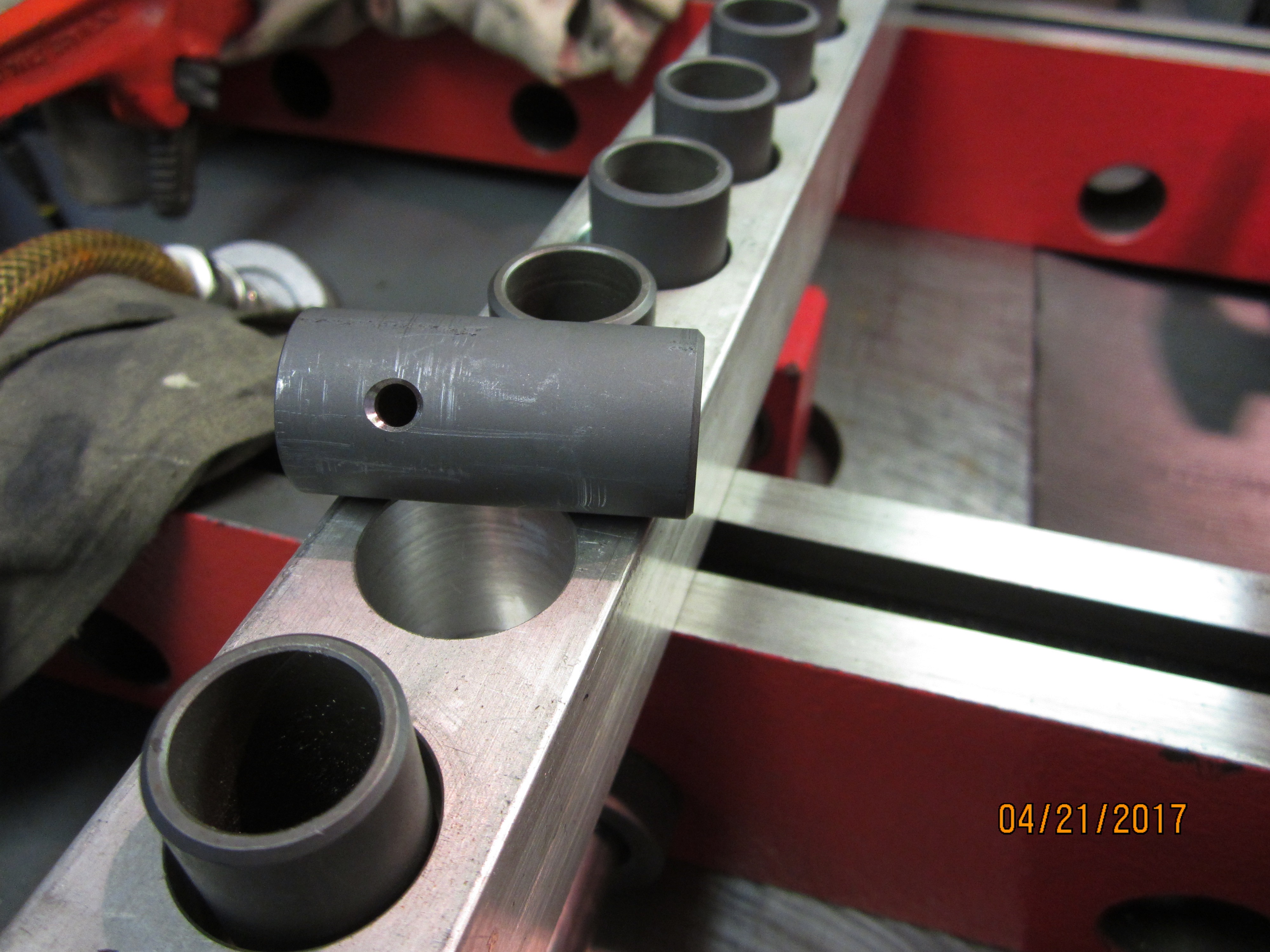
Boring
BMC tappet holes required
being able to reach nearly a foot into the block (from collet to tool
tip) and
machining a nearly blind hole at the correct 2 degree inboard
inclination from the
cylinder bore centerline. At the top of a BMC “A+” engine
tappet bore is a hole
about 3/8 inch in diameter intersecting an oil return galley within
about a
quarter inch. The pushrod passes upward through the hole and galley to
the head
inclined inboard to meet the rocker arm shaft, while oil returning from
the
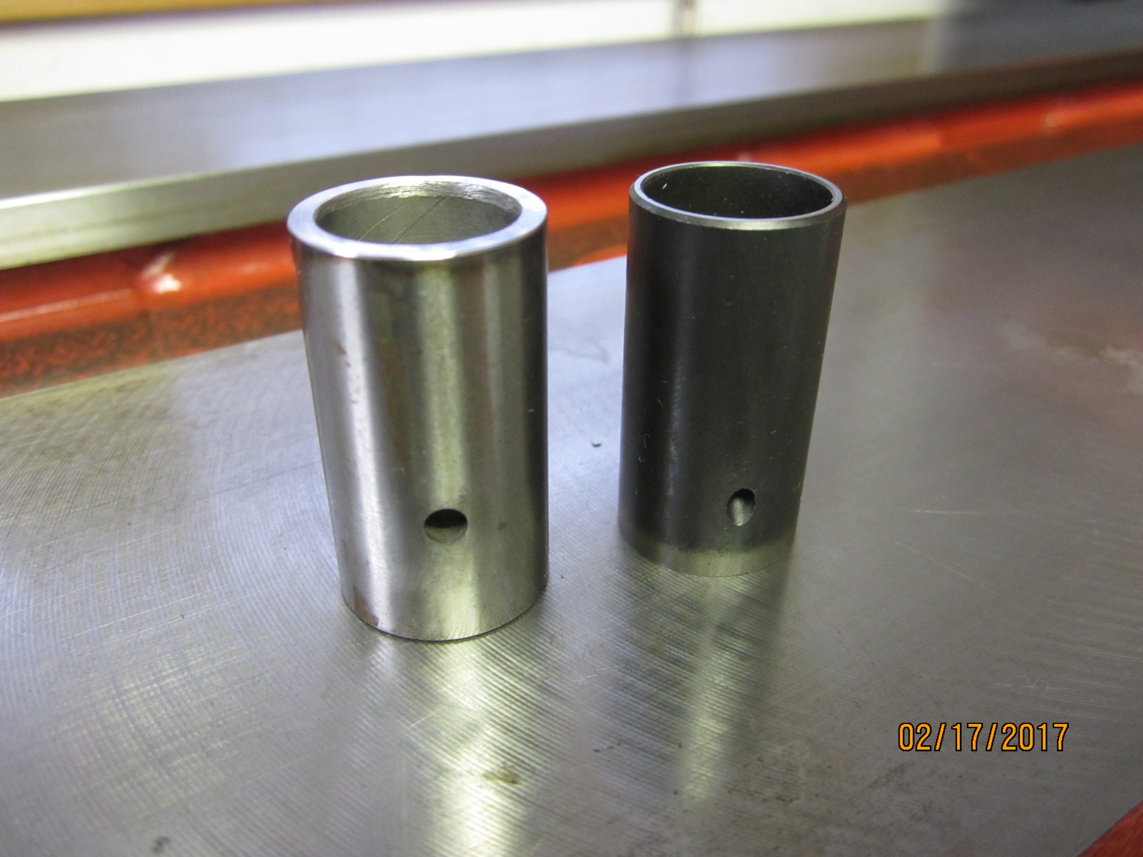
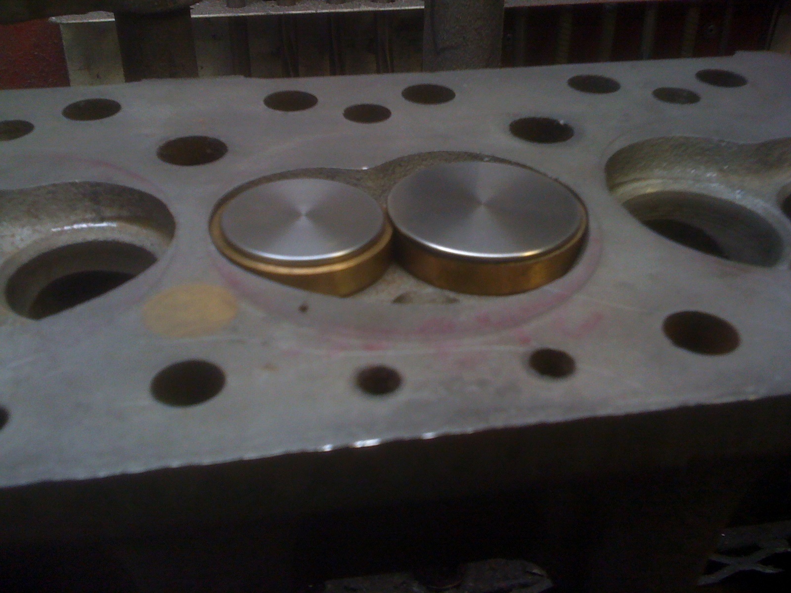
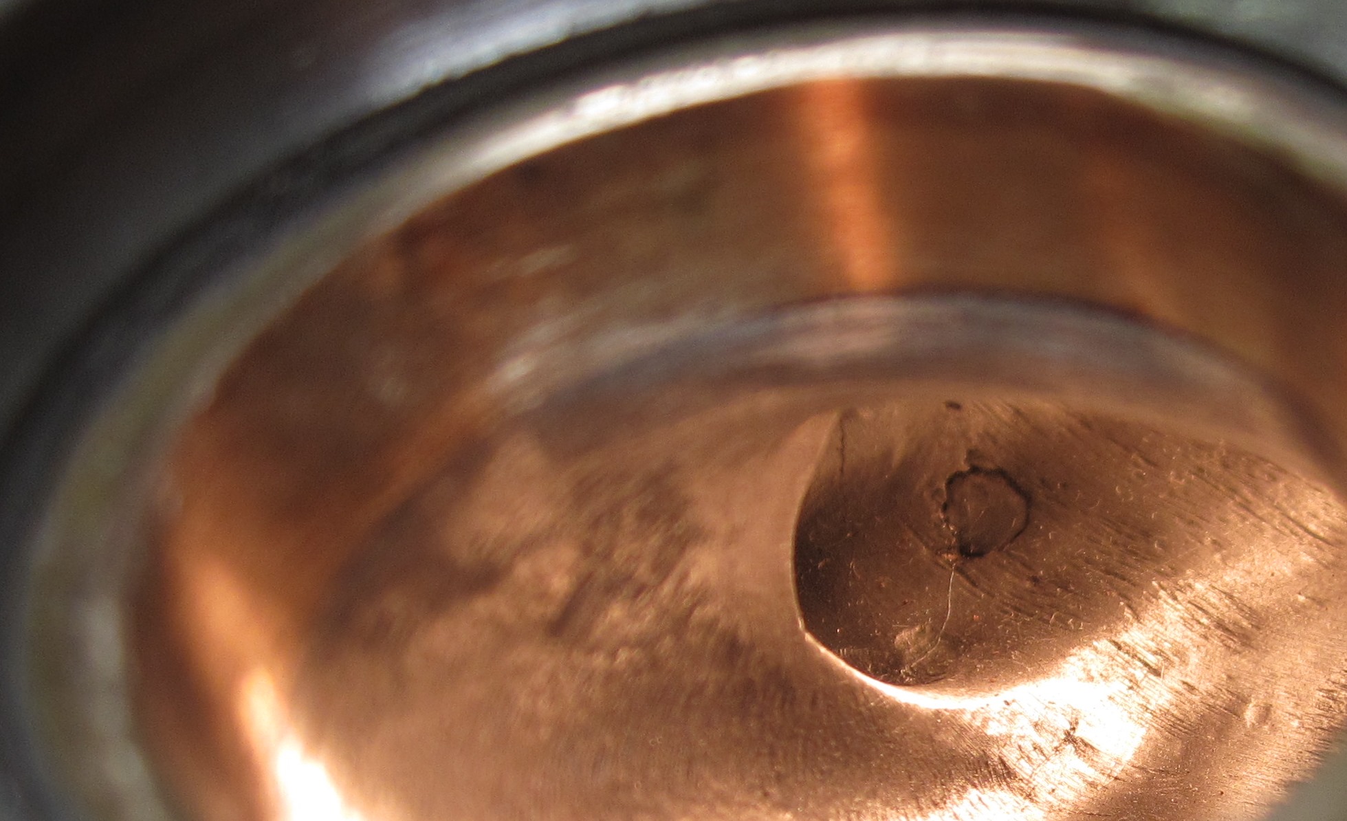
head drips down into the tappet from the galley. Oil
dripping down also fills each tappet
bucket and seeps out of a hole in the side of the tappet body
lubricating it.
The pushrod is about 1/4 inch diameter, solid cast steel, and
isn’t very strong
or stable at higher loads or speeds. That whole system is very iffy in
my
opinion and needs modification for high speed operation. One
modification made
was adding a second tappet drain hole. Shown here the tappets have been
anti
friction coated and drilled. They are racked and ready to clean. At
this point
we had 11 candidate tappets remaining of which I chose the best 8 to
install in
this engine.
Once the engine is running each tappet gains
about 30+ grams of oil weight which isn’t any good. Think of the
camshaft load
running 8 hydraulic pumps jetting oil back up the tappet bore into the
drain
galley through that small hole which is essentially plugged up by the
pushrod.
I
made
tooling similar to a BHJ Lifter-Tru
set, but suited to the BMC blind hole block. In the photo, starting on
the left
side, are two adaptor rings to locate a centering bar into cam bearing
bores.
In the central photo area is the centering round stock bar which has a
hole
pattern bored into it matching the blocks tappet holes. It locates two
dowel
pins into existing or re-bored tappet holes establishing a centerline
and axes
for machine work. In the photo, right of center are two dowel pins with
different sized ends allowing all combinations of bored and un-bored
tappet
holes to be located. They jam in tappet holes, locking the bar into a
correct
position for the next hole to be machined. Photo lower center is a lock
ring
which bolts to the blocks front surface double locking the bar from any
movement after the dowel pins are removed to insert cutting tooling.
Finishing
off the tool set, but not shown, is a precision drill and reamer. Also;
for
final sizing a custom lapping rod is used. It fits into the dowel pin
centering
holes in the locating bar which holds it very steady and at the correct
position in the same collet used to oversize the tappet hole. I also
made a
special tappet which has a scribe point exactly in its center for
marking a
line in the camshaft blank verifying correct location.
Then
I
re-bored the tappet holes
entirely into the intersecting oil galley eliminating restriction
possibly
caused by pushrod and tappet pumping motions. I used my Serdi seat and
guide
machine to do the boring job because this 1275cc BMC block (bored to
1310cc) is
so small you can treat it like a cylinder head in many fixturing
considerations. Traversing the air float head of my Serdi machine in
conjunction with my tooling is faster than setting up then moving a
milling
machine table. Chip removal from the nearly blind hole while machining
was done
by vacuum suction out the little oil galley hole. If chips are allowed
to rise
up the drill’s helix they can scar a newly made tappet bore
deeper than the
reamer or hone can remove. This is a tricky bit of machine work,
especially
finish lapping to size and then honing. The tappets are select fit to
their
bores in final engine assembly.
And
after drawing a blue print
of the BMC block’s cam area “as made” I found its
existing tappet bores were
only approximately offset equally from cam lobe centerlines. This
indicated
non-rotating tappet issues might happen. I corrected my tooling to more
accurately place each tappet against the cam lobe across the cams
length with a
proper offset to allow for rotation when ground to the appropriate
taper.
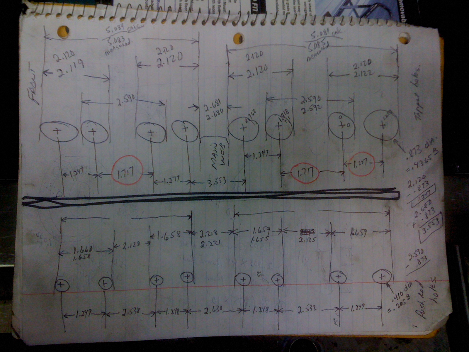
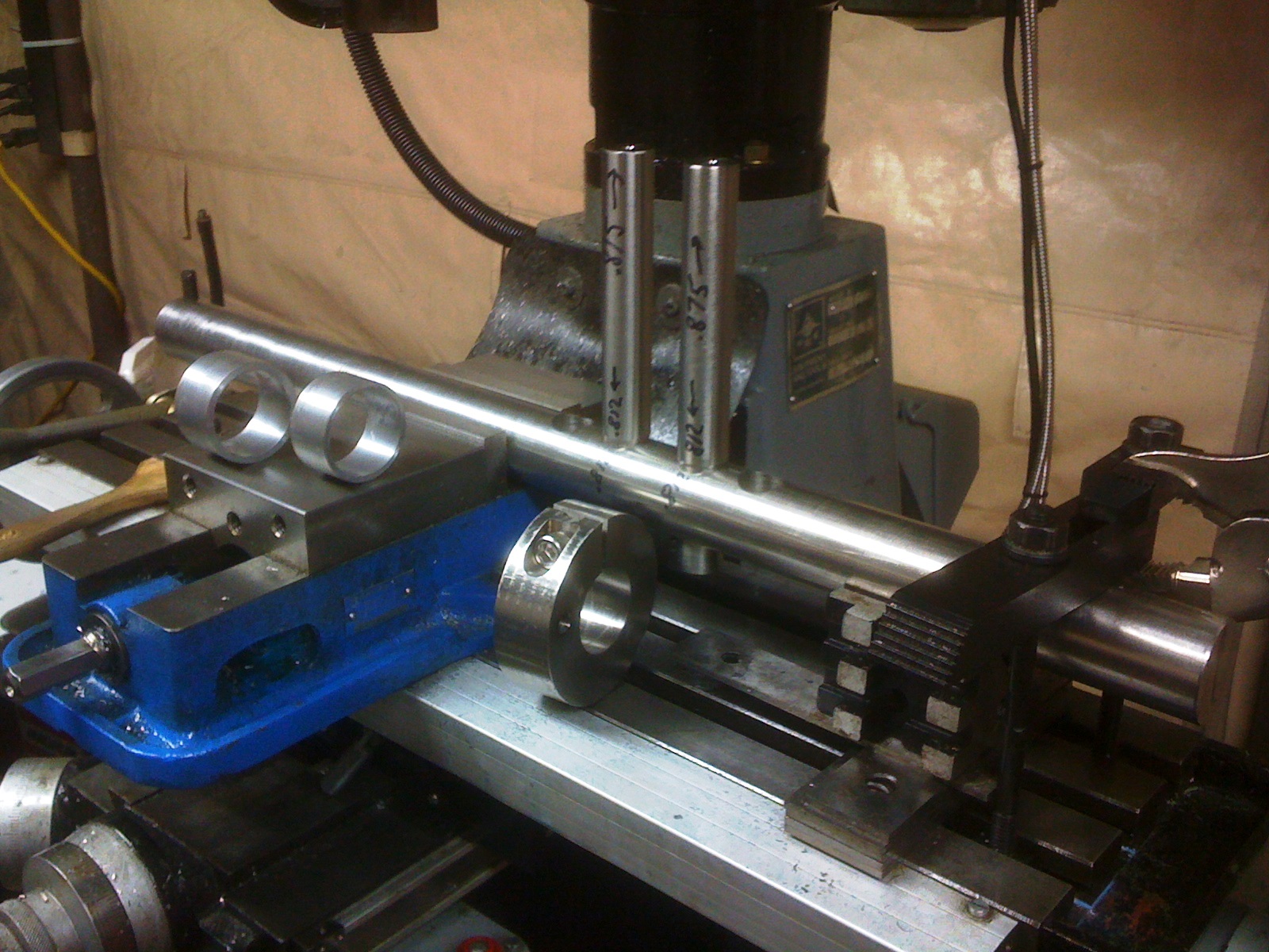
The
next major challenge with
the block is moving its pushrod holes inboard and oversizing them to
7/16th for
tubular 5/16th inch custom pushrods supplied by Smith
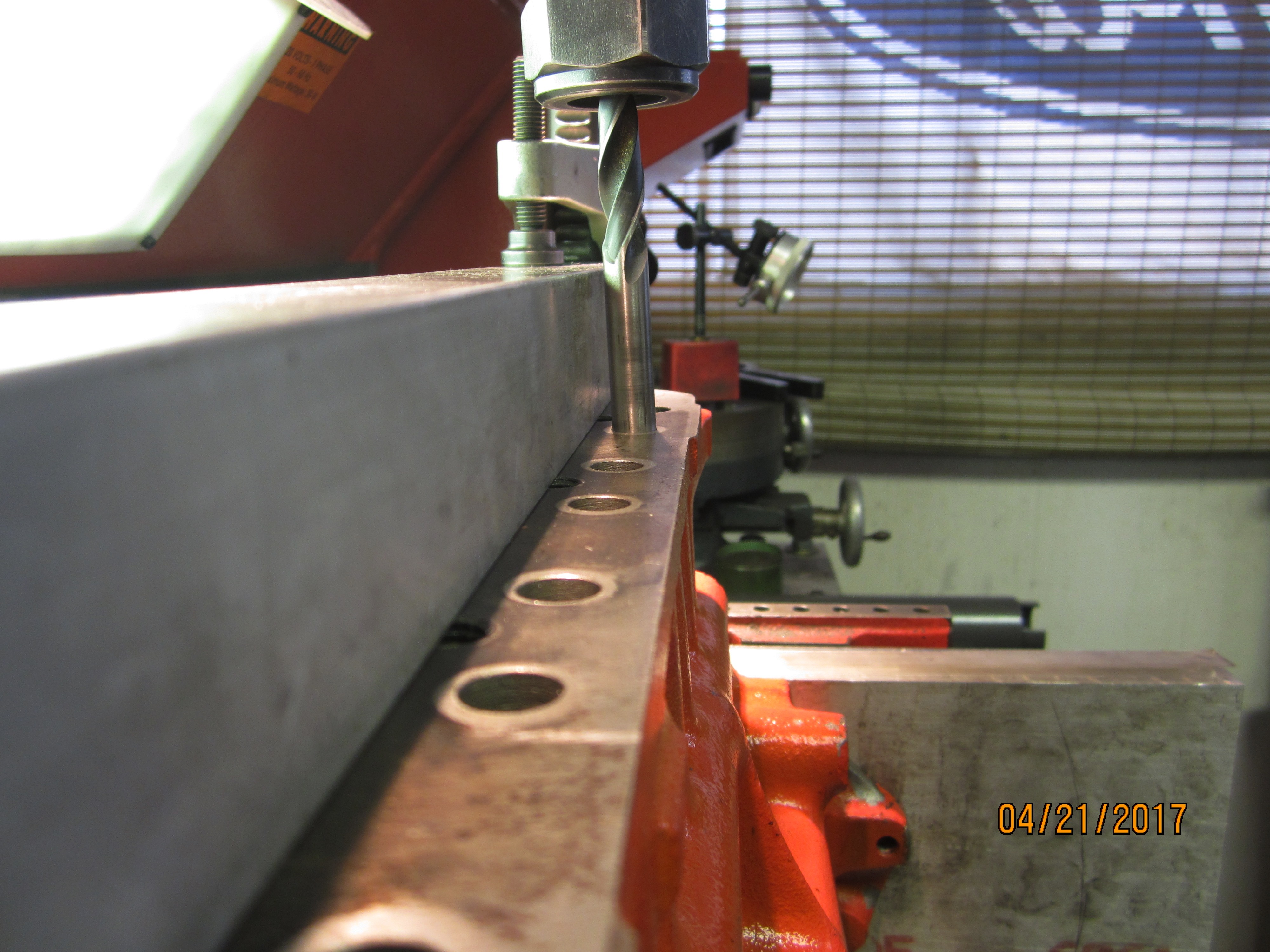
Brothers. The
hole needs to be moved, on its 2 degree inclination, measured at the
top, about
.080 or more over about a 6 inch depth. Shown in the photo below is an
initial
set up where pushrod holes are first drilled oversize to 7/16th. Then I
made a
tool change to a very long milling cutter which moved the hole over.
The
aluminum bar was a “straight edge” which located my tooling
parallel to the
crankshaft centerline while being angled inward from the cylinder
centerline.
Installing the drill upside down into the hole and collet helps better
locate
the Serdi machine air float head because my ground rod center finding
tool was
AWOL somewhere else in my shop that day.
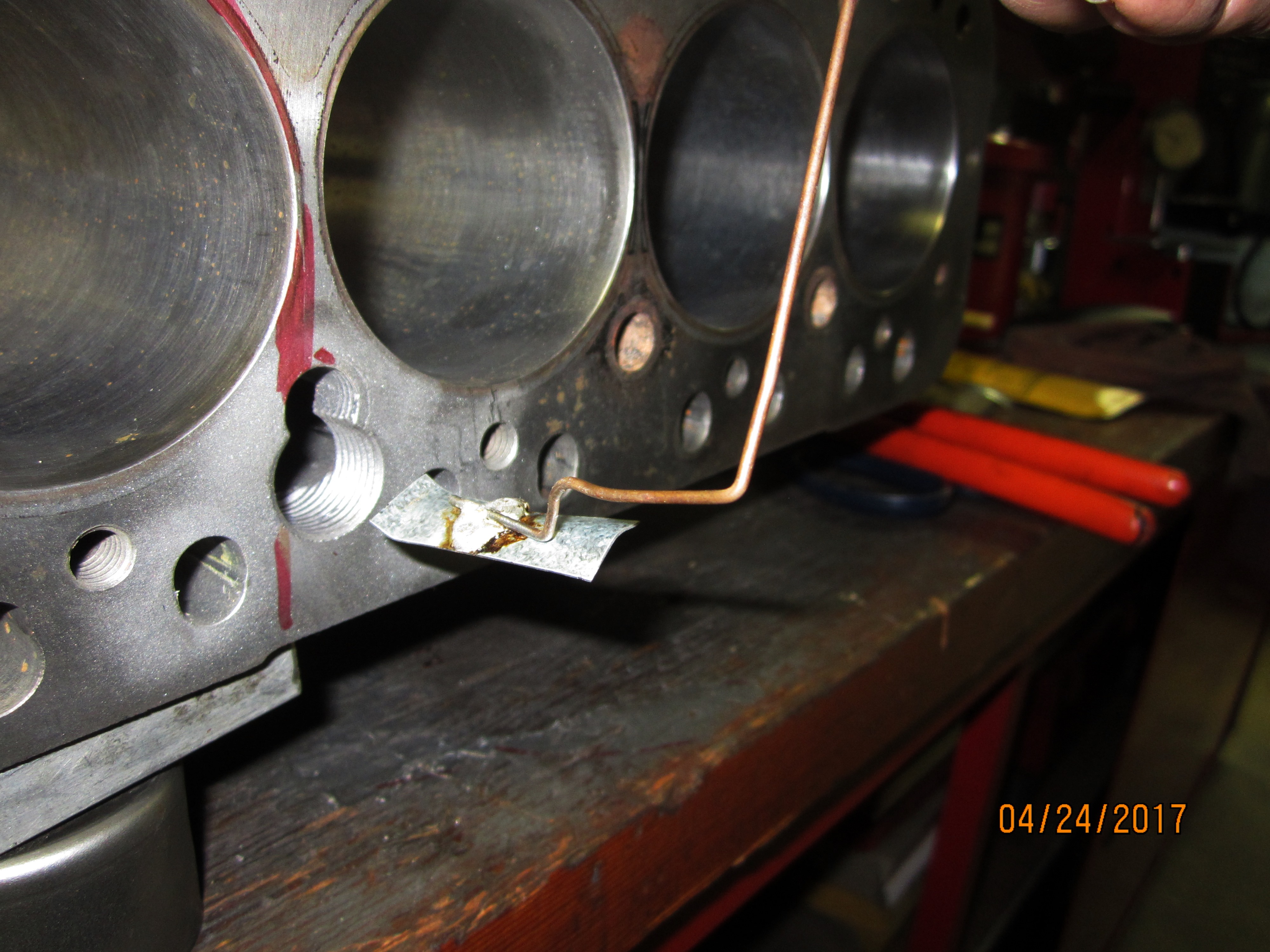
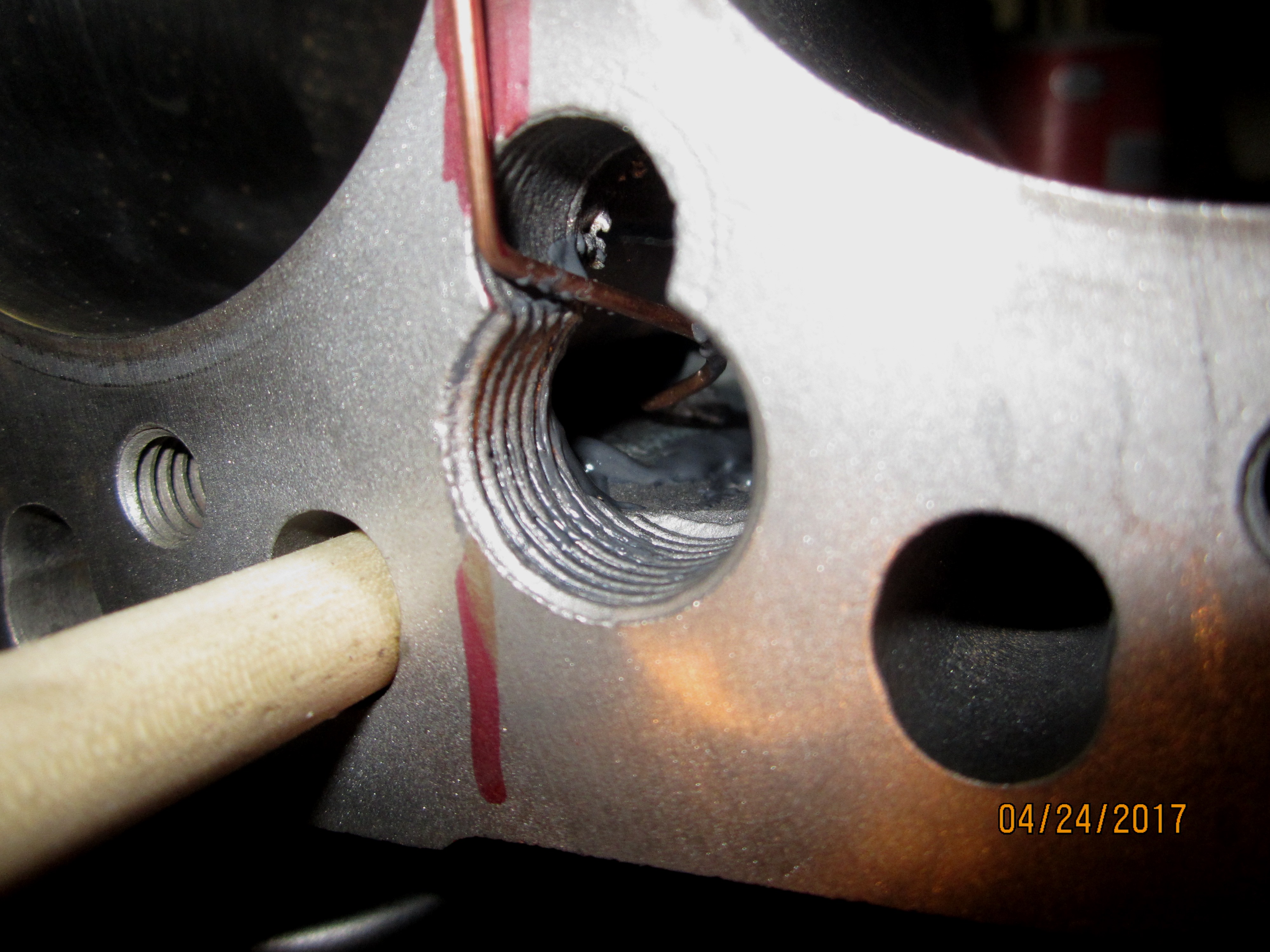
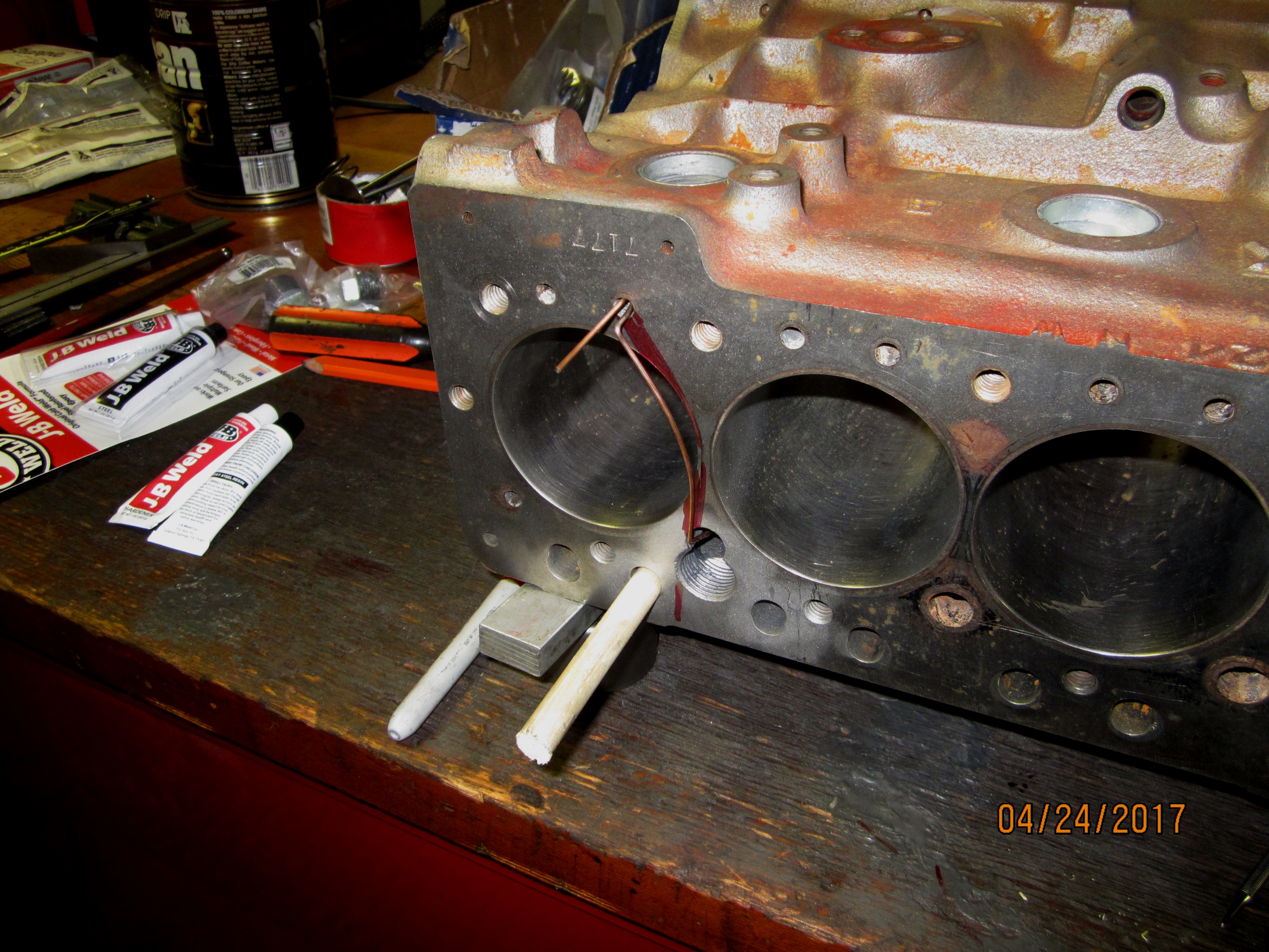
This necessary machine work resulted in
breaking into the water jacket on 3 of the 8 holes. Casting shift
seemed to
favor the front holes and thin out the rear ones. Fixing those
perforations
required drilling 3/4 inch holes in the blocks cylinder deck adjacent
to the
pushrod hole. Then sandblasting the water jacket to bare roughed up
metal,
forming thin sheet metal “patch plates” over the areas,
then epoxy cementing them
into place using wire spider legs to restrain movement over night while
curing
took place. Greased wooden dowel pins preserved the oversize pushrod
hole from
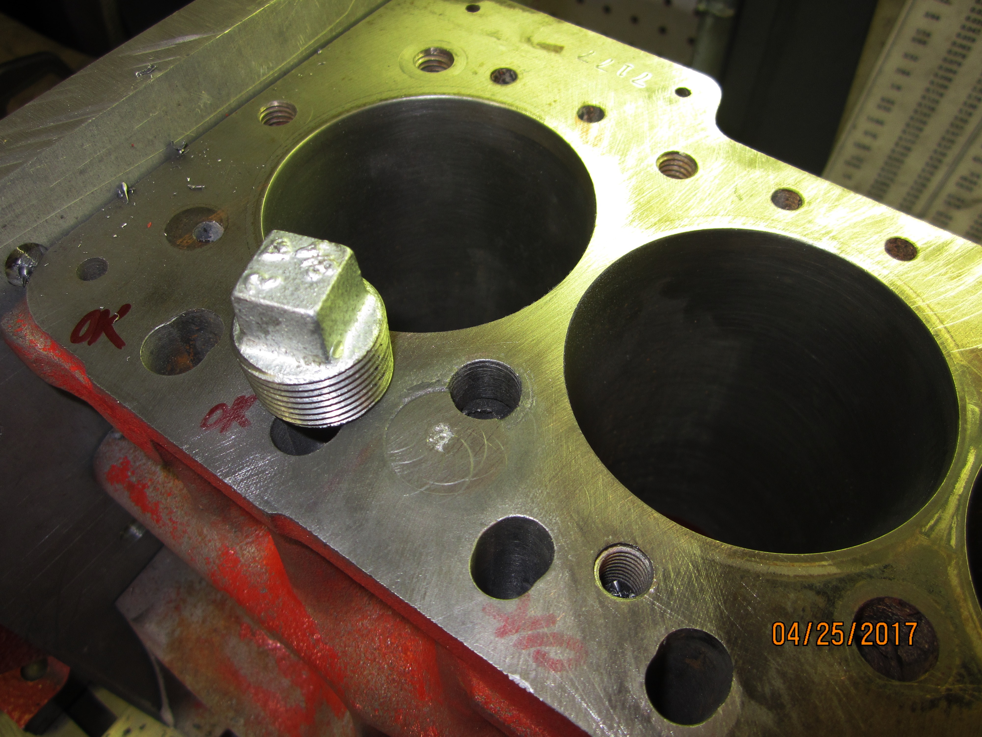
filling with excess epoxy. Then I had to plug the deck without creating
a need
to re-machine it. The existing compression height of block decking done
in
other shops had left no material for service repairs. Dressing off
square drive
pipe plugs was done with a hand file and large diamond lap stone after
rough
grinding the bulk of extra metal plug away.
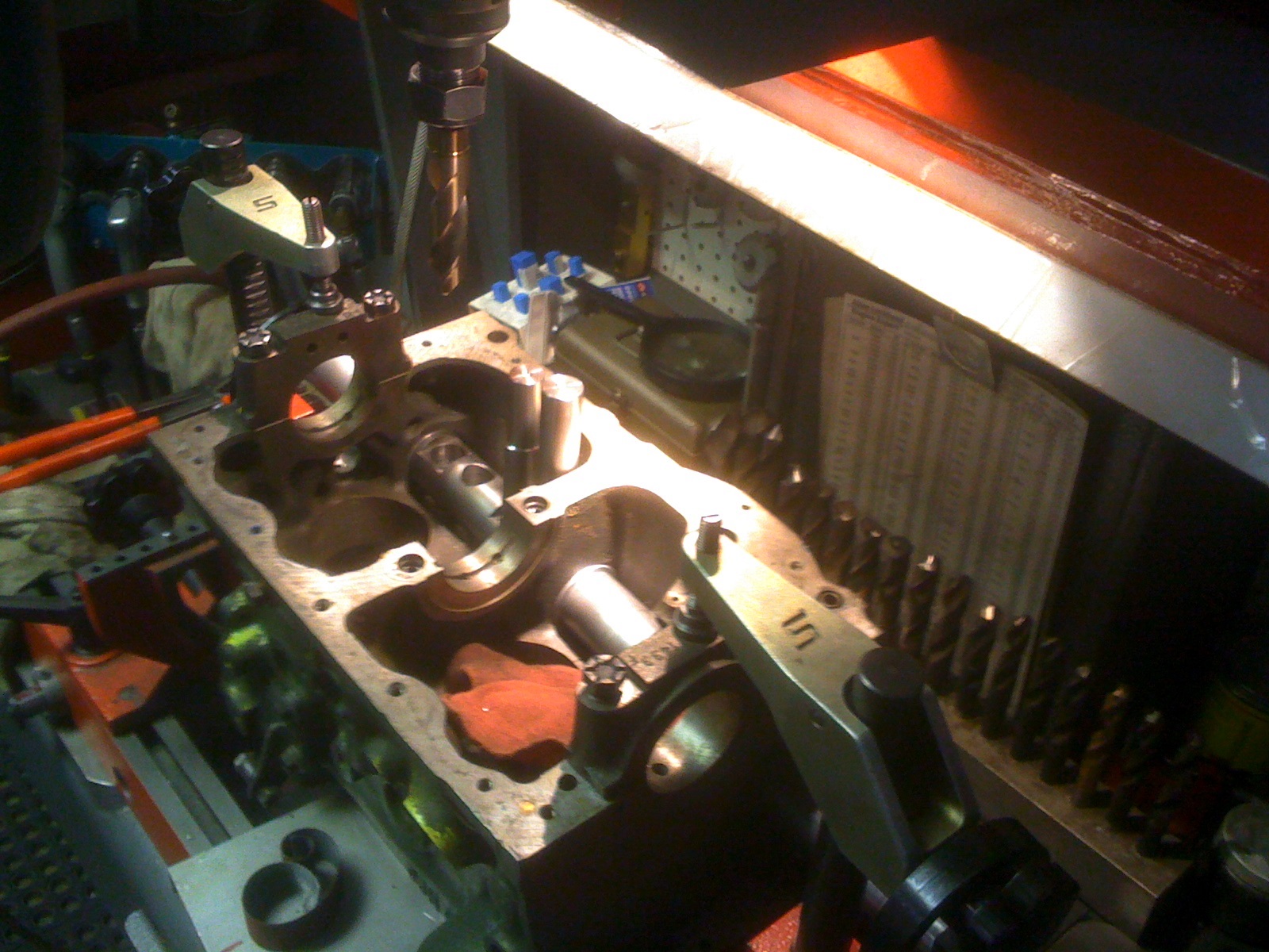
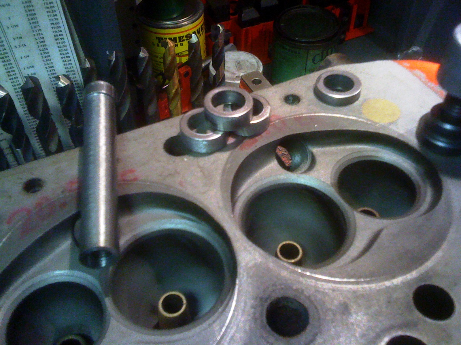
The
next block machining operation
was dowel pinning the head to the block and correcting head stud
engagement
length. The head could move on the block’s ARP stud shoulders
more than the
thickness of its gasket fire ring (Mini Mania Turbo Metro gasket
#STR1057) and
could bring its oversized valves into possible contact with the block
cylinder
walls. Therefore to assure consistent assembly location 2 hollow dowel
pins
were installed around the end studs. The dowels were lathe turned from
steel
stock. The centering tool (photo left side) was made to fit onto a
valve guide
top trimming cutter. The cutter was repurposed to machine out counter
bores to
hold the dowels. Not shown is a sandwich die to allow the valve guide
trimming
cutter to enlarge two complementary head gasket stud holes so the head
gasket,
head, and block would all register together.
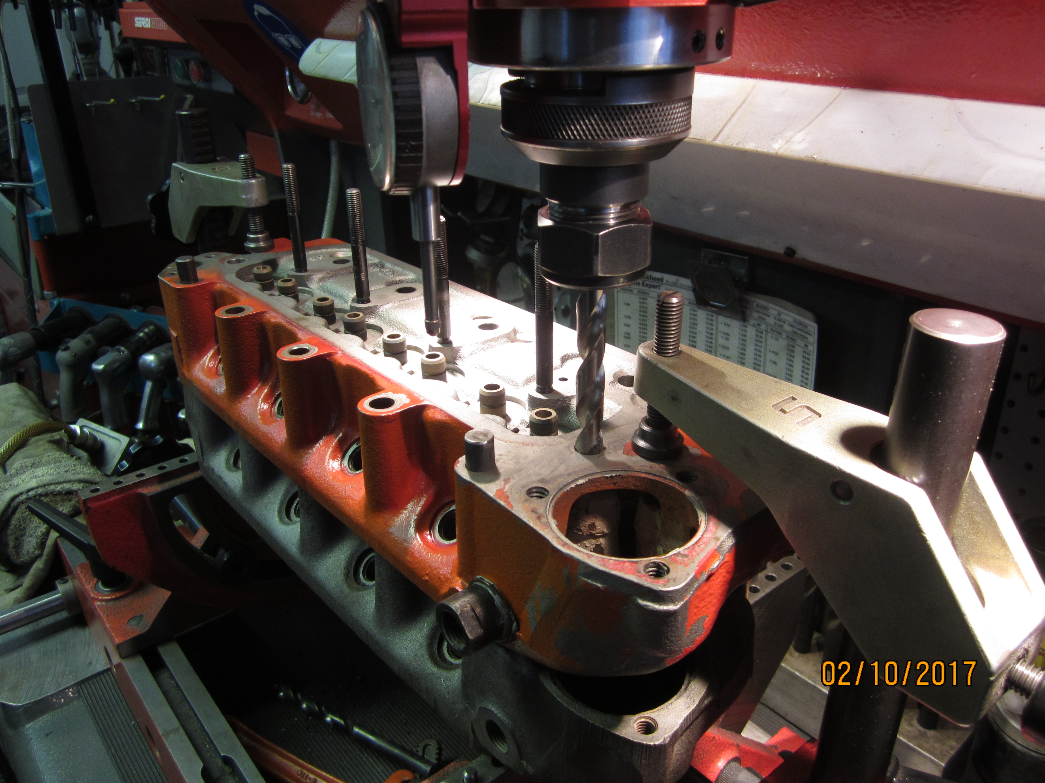
I found the head stud holes, after deck milling
by the other machine shops, only had 5-7 threads remaining in the block
so they
needed to be deepened and re-tapped allowing an HSA11-B ARP stud kit to
engage fully
8 threads deep. This was also the time to add a head stud hole to the
new head.
Passenger service BMC engines didn’t need a head bolt near the
water outlet but
racing Mini Coopers did. The BMC Factory added one stud to that area
and it has
become a standard operation to drill any head used for competition in
the same
location as the factory did. I did that
by pattern drilling through a head that had the hole already in it.
They simply
needed to be stacked up, doweled together so they remained indexed
while
machined, and a long drill passed through.
Enlargement
to 1/4 inch of all
oil passageways going to the head, including machining an oil transfer
slot in
the forward cam bearing and around the camshaft journal was done. Do
not cut
away the “dam” between an existing axial oil channel and
new radial one. You
want extra oil to go up to the head not out the front of the engine. Adding a couple of missing threaded holes
which attach the oil pump body to the block was eventually done as
well.
With significant additions, remaining block
preparations more or less followed David Visard’s book and
standard race engine
practice.
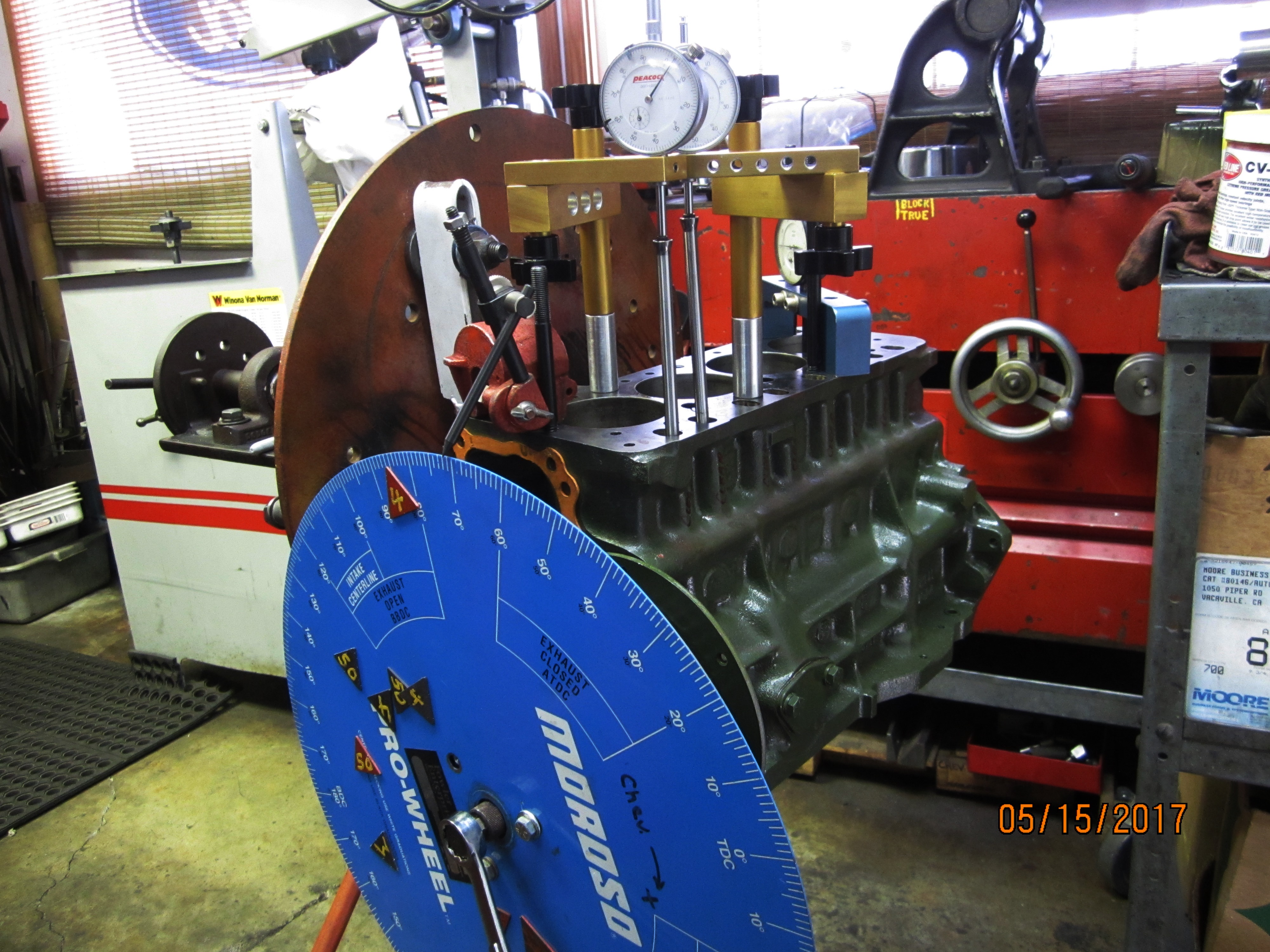
This
is the set up I use to
degree camshafts. One dial indicator resolving to .0001 is set up on a
deck
bridge to monitor TDC. A second dial is on the intake lobe pushrod
resolving to
.001 and a third indicator is on the exhaust lobe pushrod resolving to
.001.
That makes figuring out overlap timing very easy. You can just watch
the dials
and move pointed magnets on the timing wheel to stick on any degree
location
you want to count from. I have black magnets for intake and red for
exhaust. Those
basic tools came from PowerHouse (Comp Cams) many years ago and since
then were
extensively modified to become more versatile. The dial indicators came
from Peacock
and Mitutoyo. The front pulley supplied with our Swiftune DC5-2
crankshaft was
re-machined to become a hub for holding the degree wheel.
Some
additions were epoxy
bonding into the engine sump 4 large super magnets below the
transmission gears
in the path of a Mini Mania #C-AHT54 racing oil pickup.
I
used
their upgraded water pump
#GWP-187EVO with the largest stamped steel pulley I could find (much
lighter
than the aluminum version) and a two blade fan created from half of a 4
bladed
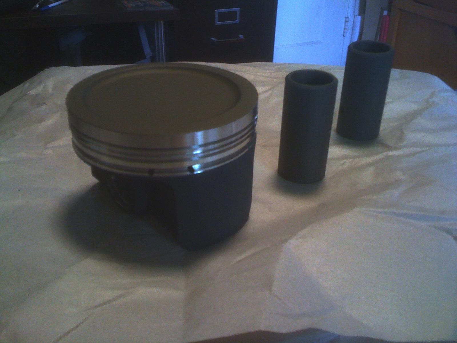
OEM fan. A #MIN500 windage tray was fitted. Swain Technology thermal
barrier
coated our piston crowns and their anti-friction coating was put on the
skirts.
Swain also coated our tappets with anti-friction material and coated
our entire
exhaust system including some heat shields I fabricated with their
“White
Lightening” compound. Swain Company was very good to work with.
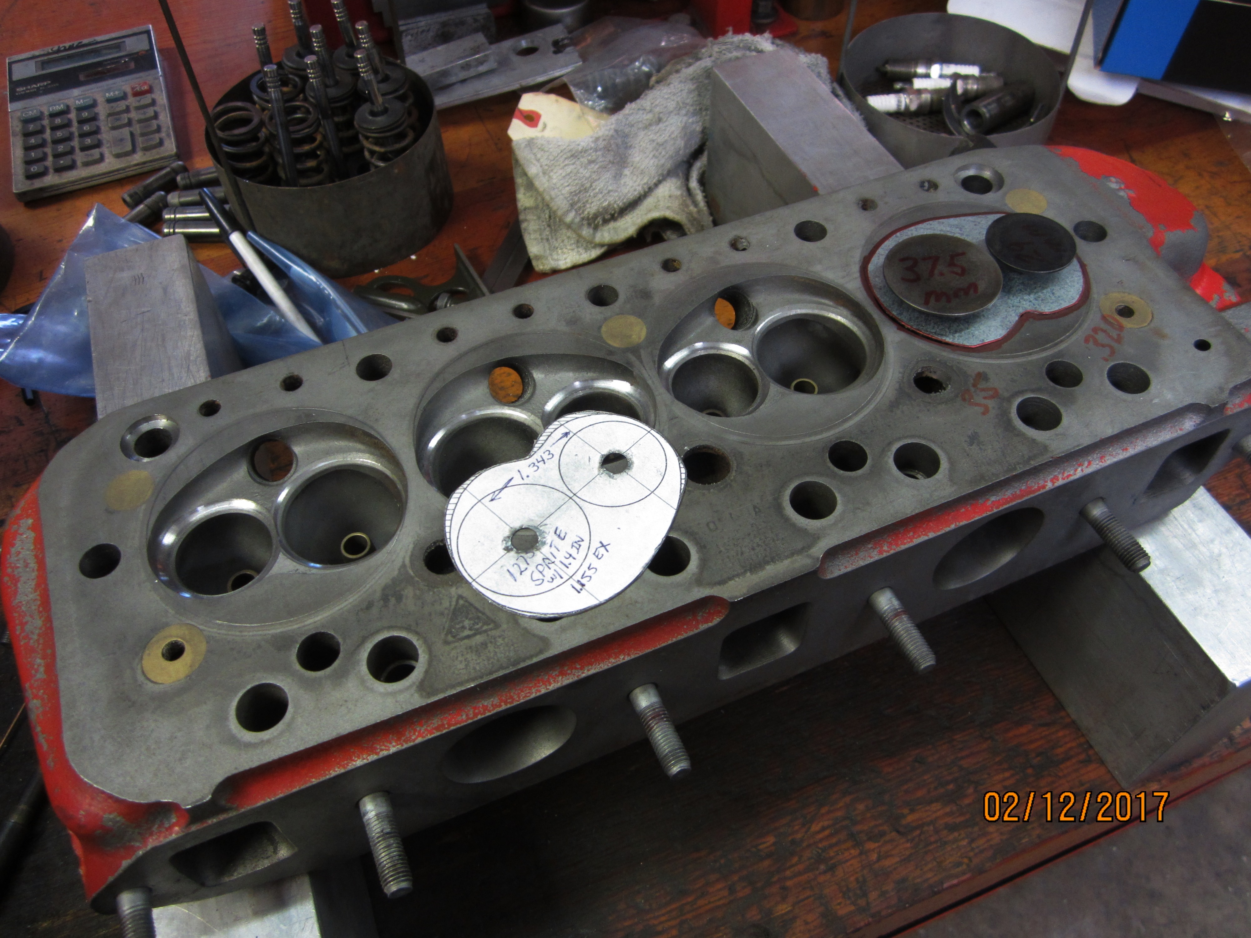
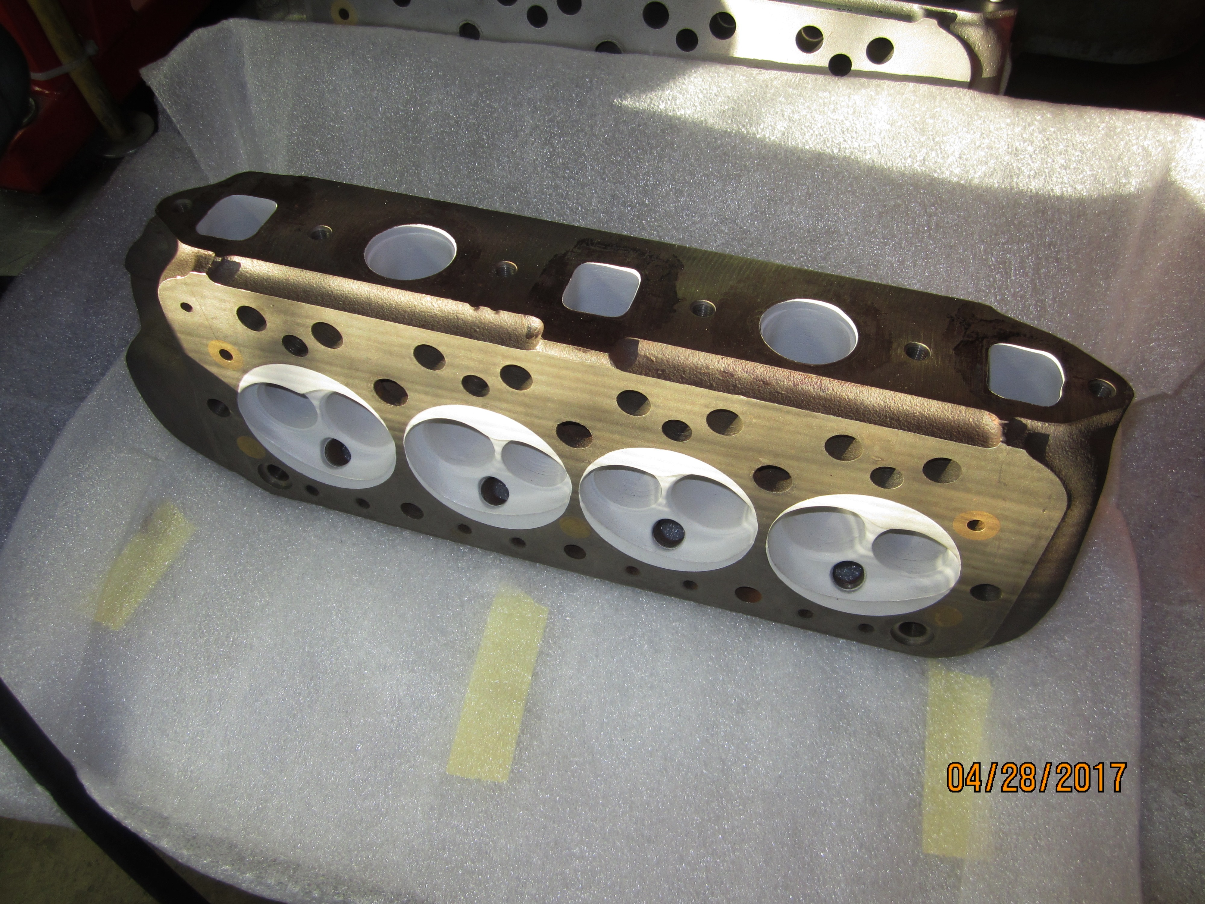
Building
a new cylinder head
from casting # 12G940 is where the magic of this engine started.
Obtaining an
RPM range needed to win, in my opinion, was not possible with
conventional Mini
Cooper hot rod valve train parts so I looked for titanium replacements.
I
determined building a head around titanium parts which would have
smaller high
velocity ports, improved thermal dynamics and lubrication, and taller
springs
more suited to endurance stability could be a winning strategy.
SuperTech
provided Honda 5.5mm
stem diameter RSX valves, guides, lash caps, and seals. Those valves
would
nicely fit into the BMC combustion chamber after re-profiling the
chamber by
following steel patterns I made which located off the valve guides.
Shown here
are the “Longman” style valves in a Visard designed chamber
against a
non-ported casting.
Lash
caps for the Honda valves would
reduce contact loads at the rocker arm below OEM part values. With a
bit of
work Honda B/H series guides were made to fit the BMC head.
SuperTech’s BMW M3
racing valve springs were selected with complementary retainers and
locks. RSX
valves are a bit more than an inch longer than OEM Mini Cooper valves
so I
fabricated three systems of aluminum heat sinks which would fit into
that “extra”
space. One plate would fit against the
head, be restrained by rocker arm studs, allow cooling oil to pass
under and around
it, while also forming a base platform for our engines rocker arm
stands. It
has a simple drilled oil passageway for rocker arm shaft lubrication.
The
second system is formed of 8 aluminum collars press fit around the
valve guides
and tightly compressed against the head while bonding with thermally
conductive
epoxy. These strengthen the guides and conduct heat out of the guide
into the head
while holding spring seat cups. They also set installed height for the
BMW
springs. The photo below shows those parts trial fit so pushrod
clearance might
be laid out then machined in the plate first mentioned.
Necessary valve spring pressure was calculated
in Performance Trends software then set at 60lbs on the seat and 170lbs
– 180lbs
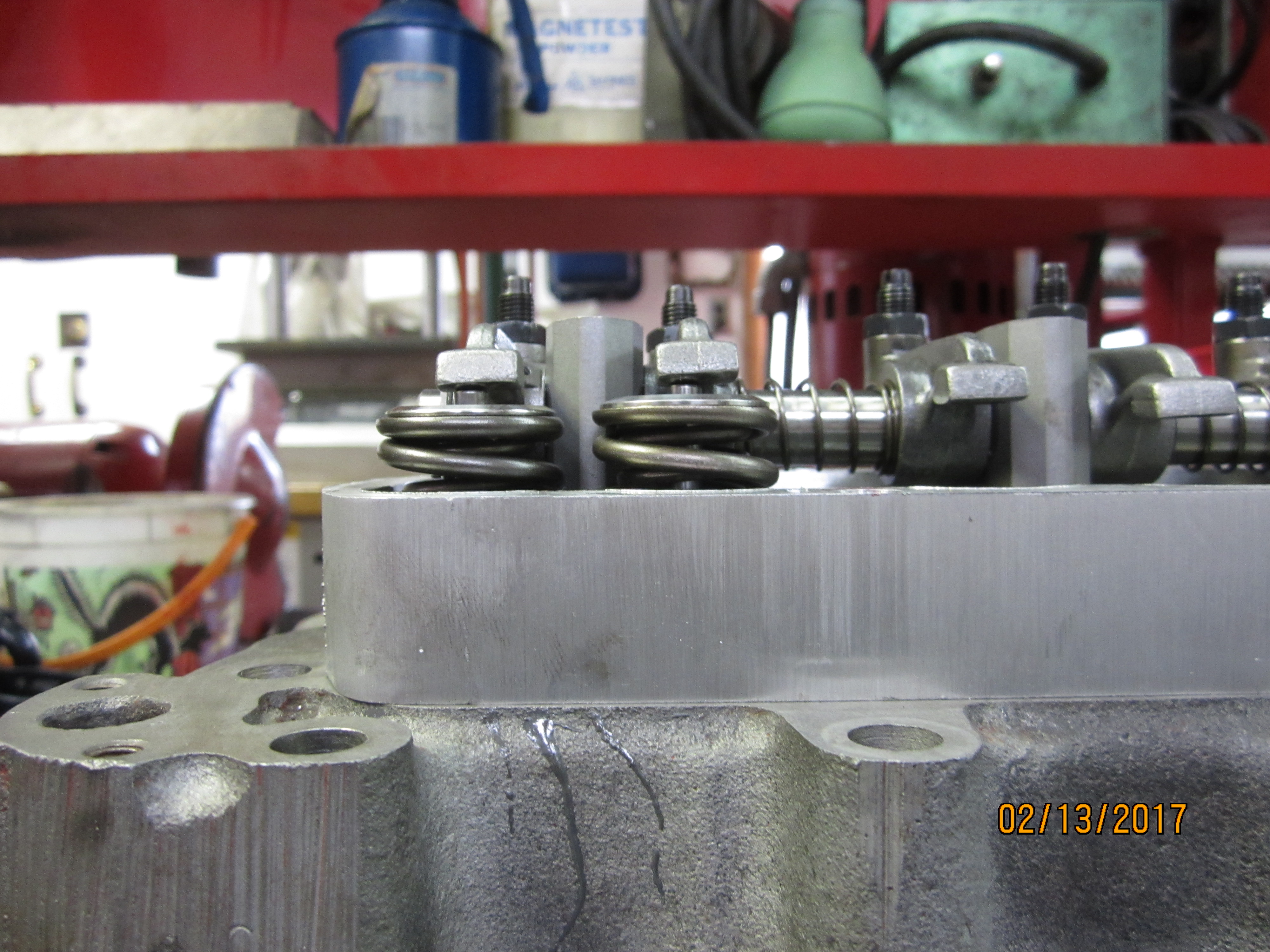
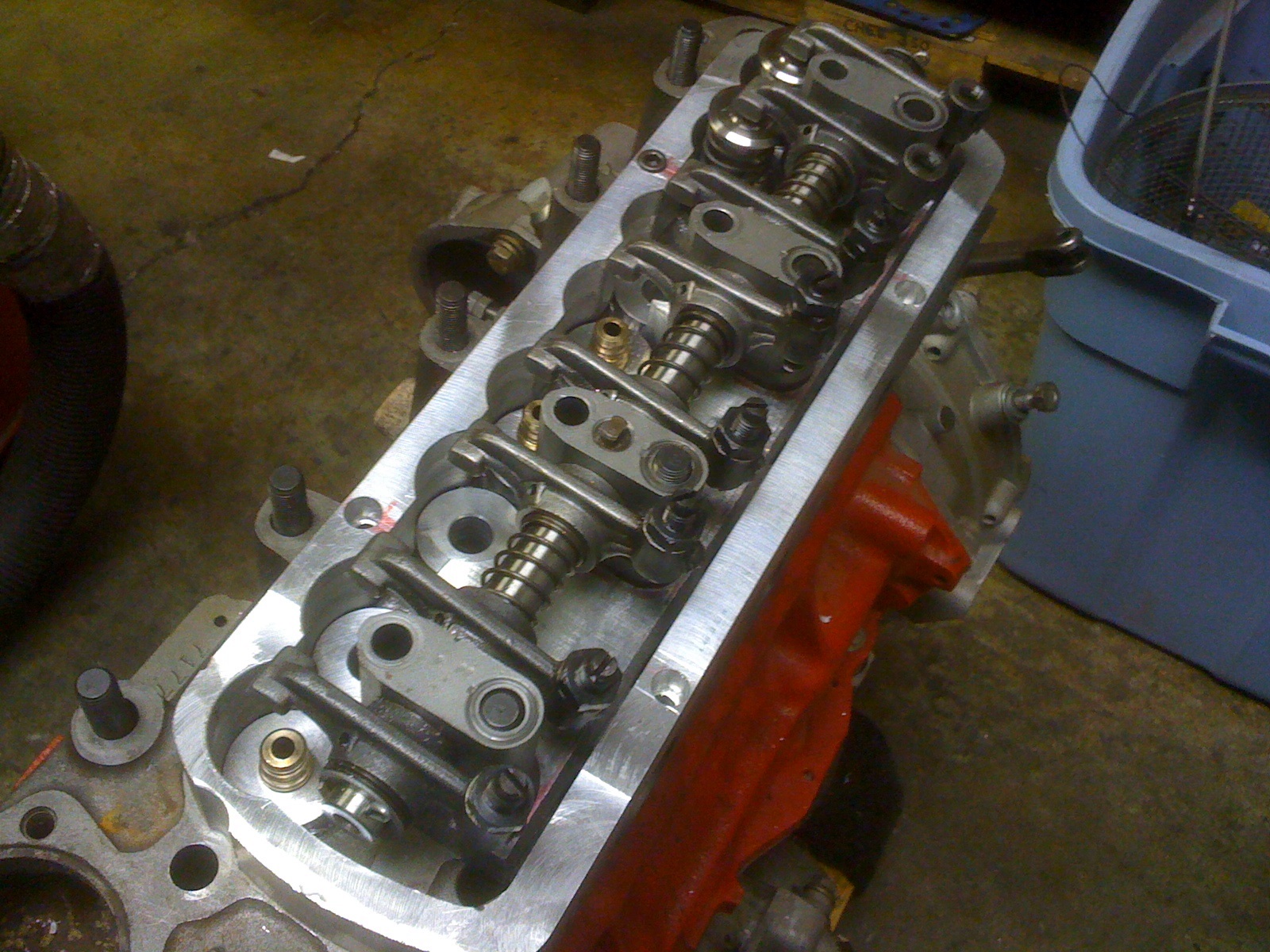
over the nose. The third system is a forged aluminum rocker arm cover
spacer
which raises the cover up allowing room for 1.5 to 1 ratio steel
rockers to
move. The valve cover spacer is notched to fit closely to the springs
so
radiated heat is conducted out of the engine to air or into engine oil. When batches of rocker arms were examined,
OEM and aftermarket, I found them erratic about placement of oil spray
holes.
Some had spray holes and some didn’t, but none sprayed at
anything useful.
There was very little room for rocker arm stands in this engine. Note
that the
stands have been profiled round on the pushrod side instead of being
squared
off. Solid shims replaced springs on the shaft itself to positively
locate the
rocker arm tip over the valve stem lash cap. It took cherry picking 3
sets of
rocker arms to get a set more or less the same. In the end, alignment
was
almost acceptable but not what I’d call “good”.
This photo shows typical misalignment that must be
corrected.
I
fabricated an oil spray bar
system pointed at the valve stem tip lash caps which will subsequently
flood
the entire rocker box area. It is installed above the rocker arm shaft
assembly. Oil is metered to the spray bar by a #56 Ford carburetor jet
held
captive below the rocker arm stand-to-shaft spray bar fitting. Spray
bar holes
are #72 drill size. Unmetered oil from the rocker arm squirt holes is
allowed
to spray wherever it ends up. I believe in operation the springs run
about half
submerged in oil acting as coolant. After
the Canadian / American Challenge National race the valve train was
inspected.
No wear or change in rockers, springs, lash caps, clearances or
pressures was
measurable.
Head
porting was minimal but
yielded flow numbers nearly as good or better than our
“Longman” head while
using slightly smaller (37mm IN and 30mm EX) titanium valves. Special
valve
seat material isn’t needed because the seats don’t get very
hot compared to
typical non-coated castings. However I installed beryllium copper seats
anyway.
The photo accurately shows there is zero extra room for the seat
installation.
The
head’s combustion chambers
and ports were thermal barrier coated by Calico Coatings, who are also
very
nice people to deal with. After all porting and modification machine
work was
completed and just moments before this head was packed to be shipped to
Calico,
several small casting pits were discovered in the roof of an intake
port which
were impossible to reach easily. While the head passed a vacuum test I
became
nervous the pits would open up to water in racing service.
I milled a large hole in the top of the head,
inspected the back inside of the castings internal surface for
corrosion damage
or a thin spot, and then installed two Lock-n-Stitch repair pins which
removed
the pit and surrounding metal (which appeared to be in fine condition)
for
security. Then I plugged the top of the head similarly to how I fixed
the block
deck. This led to re-pressure testing at
30lbs both engine block and head castings when torqued together for
cooling
system sealing integrity.
Calico
Coatings made extra
efforts to stay on my assembly time schedule by returning a finished
coating
job to us by our previously agreed date, despite my delay in shipping
to them.
They were generally “heads up” in all regards, also more
than fair by charging us
only what was originally quoted.
Calico
also coated our intake
manifold. By not allowing excessive exhaust heat to enter the head
casting,
elimination of a water bypass system is possible. Minimization of
combustion
heat to the oil via the piston was also accomplished with coatings.
Subsequent
testing indicated an external oil cooler isn’t really needed now.
* Do you dyno your engine builds? Do you know the HP, torque and
compression
ratio of the engine?
* Anything extra to add?
Some
engines I will run on an
inertial dyno at a track if it’s easy and we have time for fun.
Otherwise I let
track speed data tell me how strong an engine is. In this case other
thermodynamic testing was more important to investigate than chasing a
dyno HP
result so we ran this engine a lot doing that. I found in a half dozen
operation
cycles at 75 lbs initial oil pressure our water temperature rises from
ambient
at idle to 215 degrees F at 6000 RPM after 22 minutes run time,
stabilizing at
210 degrees F at 7000 RPM after the 23rd minute for as long as the
engine was
run thereafter. Twenty to thirty minute testing cycles simulated
typical race
duration. Oil pressure dropped to 55 lbs by the end of testing.
Pyrometer
temperature (sender about 10 inches down the center header tube from
the
exhaust header flange) peaked at 1600 degrees F. Tests were run with
the engine
installed in its chassis.
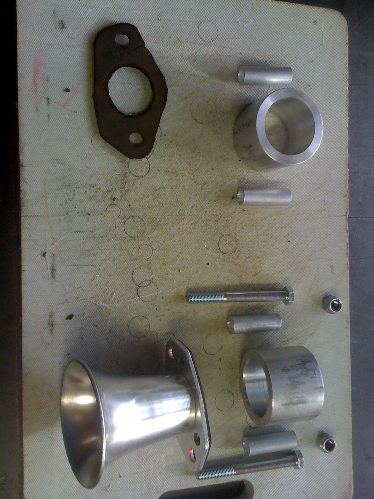
Because
time for “on track”
testing had run out we made a few hot laps around the neighborhood
where my
machine shop is located. That revealed a flat spot in acceleration
between 4500
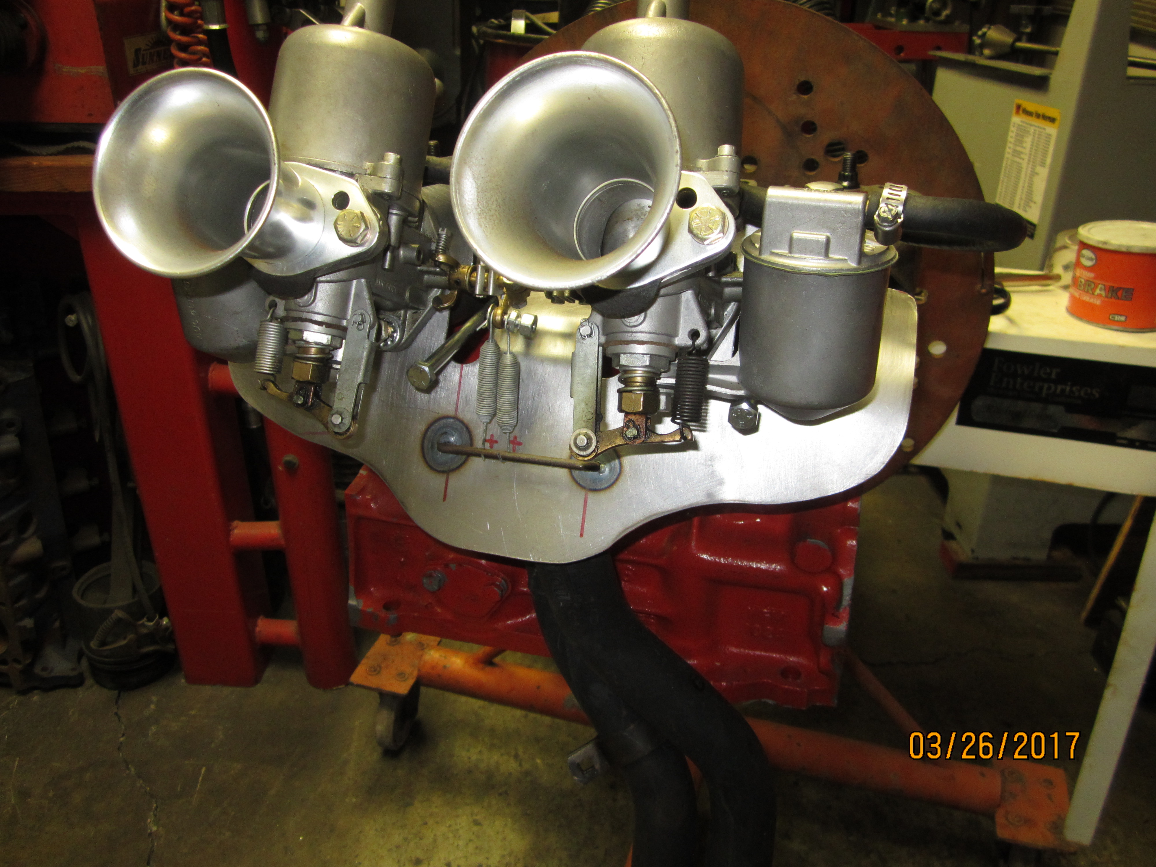
- 5000 RPM. I felt carburetor reversion was occurring so I made
velocity stack
extenders to increase the mass of air moving forward into the
carburetor vs.
the mass of air trying to come back out from camshaft timing spit back.
The
parts shown in the photograph were epoxy cast into a two monolithic
blocks for
ease in assembly to the SU carburetor pair. This added volume of air
eliminated
the acceleration flat spot.
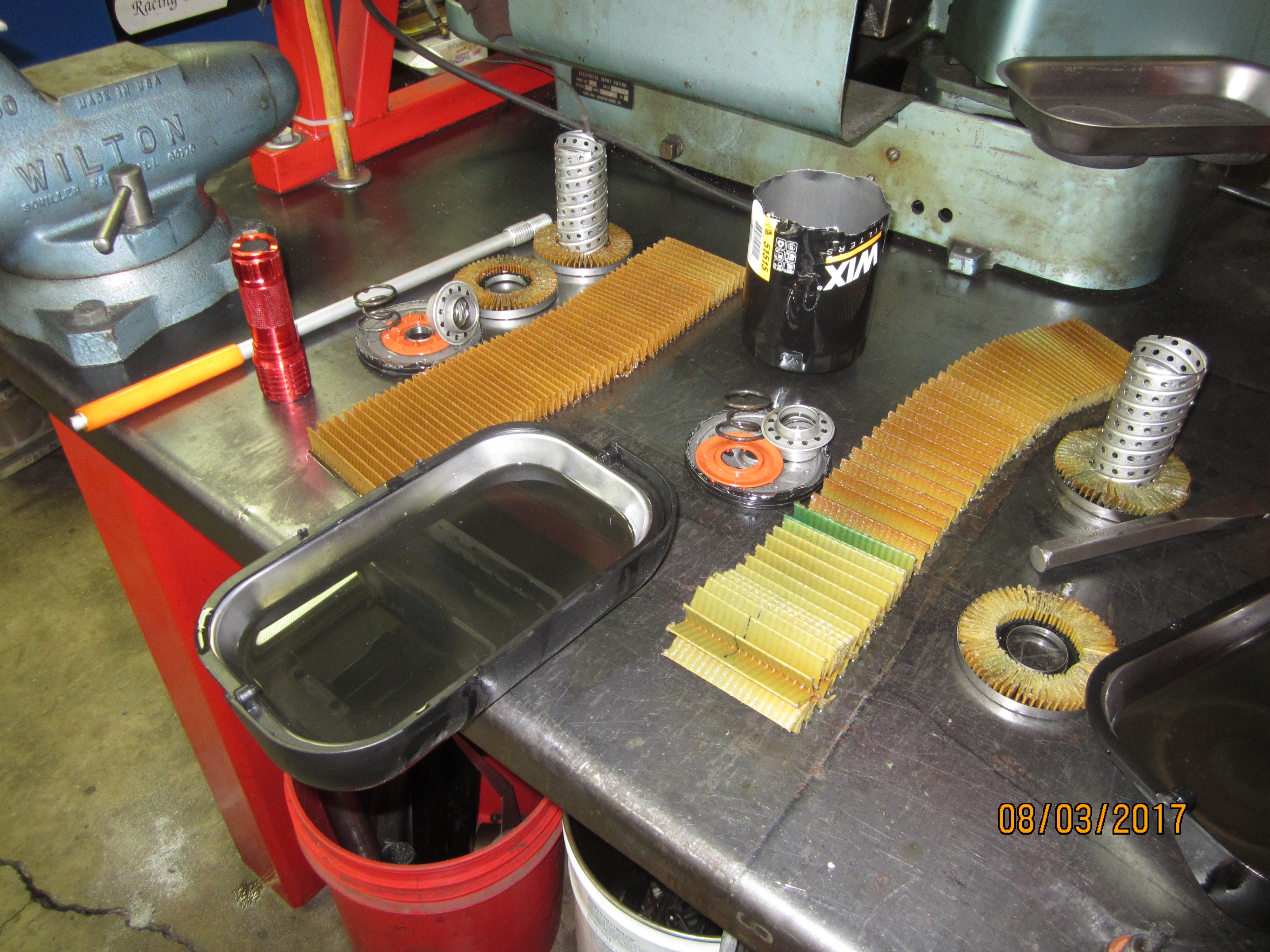
Early
in testing the camshaft
and tappets failed completely. Seven of the eight lobes were
essentially gone.
Two tappets had rubbed through to contact their pushrod ends. Typical
causes
were investigated and ruled out. The engine, gear box, and final drive
was
stripped and examined closely. Super magnets placed ahead of the oil
pickup saved
bearings, gears, and piston skirts nicely. Note the nearly clean oil
filter
media found in the photo below when the engine was disassembled for
failure
analysis.
Nothing
was damaged except the
cam and tappets. Because any specific cause of failure was uncertain we
elected
to forgo further metallurgical diagnosis to take a more certain
solution path
of upgrading to ceramic tappets. Ceramic tappets are compatible with
any cam
blank, require very little lubrication compared to conventional
tappets, don’t
need a break in cycle or ZPD additive, and can be moved from lobe to
lobe later
on if needed. But ceramic tappets cannot be run loose or run into valve
float.
Ceramic tappets cannot be allowed to pound freely against the camshaft
so
spring forces must be carefully selected for the RPM range an engine
will
achieve. I asked Bill Smith of
Cedarville Utah (no relation to Smith Brothers pushrod company) to make
a set
which would interface with an identical replacement camshaft but
eliminate the
BMC / Ford bucket style design allowing a set of shorter pushrods to be
re-fabricated
by Smith Brothers. Those parts eventually arrived – beautiful
parts indeed. Ceramic
tappets look like standard solid lifters but have hollow centers, are
very
light, just 3 grams heavier than the Ford 427cid bucket tappet, but
eliminated
tappet oil weight gain so their dynamic loading is much improved.
After
the engine was reassembled
oil pressure test cycling resumed attempting to learn the lowest
possible
pressure which the engine could survive on. I’d noted more
pressure drop than I
liked from “cold to hot” was occurring. After another half
dozen run cycles it
became apparent our “upgraded” race pump obtained from
usual BMC sources was
not performing well. When pressures dropped below 30lbs at 7000 RPM and
15lbs
at idle in half hour test cycles the engine was again removed and
stripped for
examination. I found both oil pump mounting bolts were loose and one of
the
screws holding the pump body together had been blown apart. We surmised
jerk
from the cams aggressive profile was overloading the pump fastening
system.
Looking inside the pump for end play (or lack of end float issues) I
found odd
wear patterns like the impellor was bouncing around. At that point I
researched
BMC oil pump history finding older models had used more retaining bolts
than
our block was drilled for. So I drilled our block for the “extra
holes”, cross
drilled fasteners for safety wire, and began to modify several new
“race pumps”
from various vendors for better sealing and retention to the block.
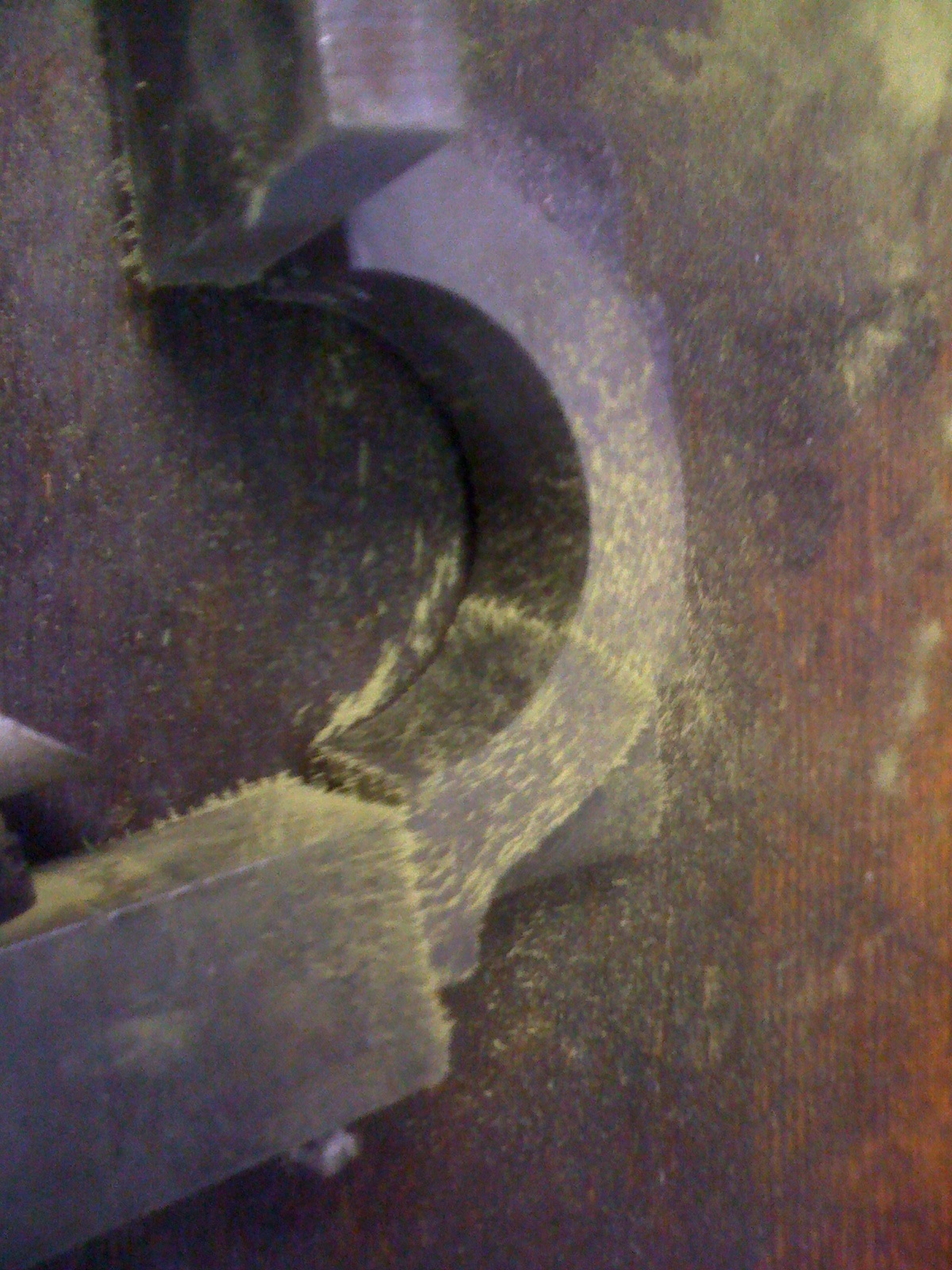
Additional
mounting holes would be placed where the weld material was added to
these
castings shown in the photograph.
Along
that path I found Brian
Waters Racing who sells a true BMC “A+” race pump –
it is better in every way –
so I junked what I was modifying and ordered one from him.
.
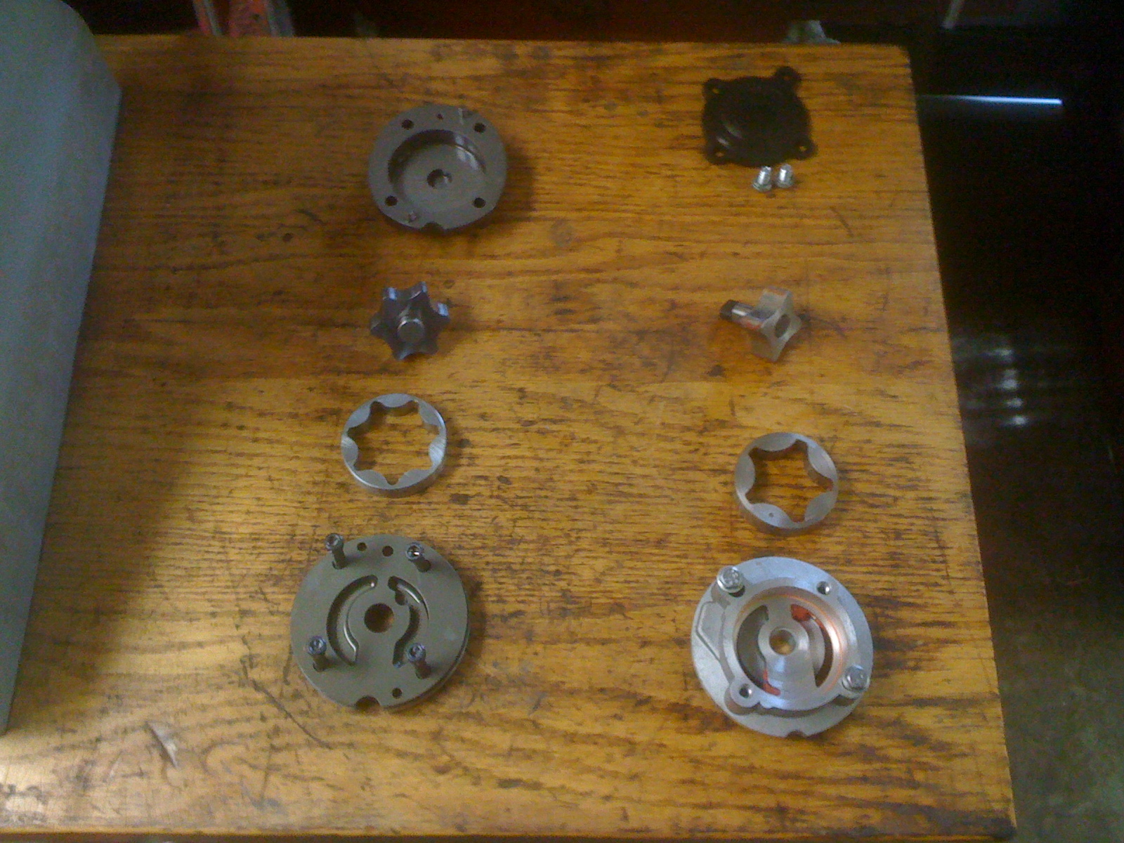
Brian’s
disassembled pump parts
are on the left side and a generic “race pump” from typical
vendors is on the
right in the following photo.
0
BWR
(Brian Waters Racing) also
sells actual ACL competition Mini Cooper crankshaft main bearings (The
Swiftune
crank uses Honda Accord CB1223-P rod bearings). So I ordered a couple
of sets
of those too. I installed main shells
providing a 360 degree oil channel. These are not to be confused with
regular
production ACL bearings sold by most vendors as the high performance
Mini
Cooper bearing.
When
the lower end of the engine
was stripped for bearing replacement after the new oil pump was
installed I was
shocked to find existing bearings were in near perfect condition after
being
run at such low pressure for as long and often as I’d been doing.
And the
ceramic tappets and cam were also in “as new” condition.
All good news
considering the National Canadian / American Challange race was just a
week
away.
However
a main cap next to the flywheel
was broken. It fell out in my hands when the ARP main studs were
loosened. It
immediately failed a magniflux inspection, then became two half caps
with a
slight tug.
We
surmised a huge clutch
shudder coupled with a very heavy OEM flywheel, which had been in the
car after
it was worked on by the other shops, had weakened the cap before a
Swiftune
Feather light unit was installed (which fixed the shudder entirely).
The
Swiftune set up removes more than 4-1/2 pounds unsupported cantilevered
weight off
the crankshaft. The remaining main caps were magnetic particle
inspected and
found to be “iffy” but I reused them anyway. The front cap
is weak because of
holes drilled into it for timing cover fastener attachment.
If I build another BMC Mini Cooper engine
I’ll
not fuss with the stock caps at all and install billet steel
replacements. In
this case another rear main cap from a different block was fitted and
the
engine re-installed for testing to resume.
I
can
mention in our testing
process Redline 50w oil performed well. We also tried Brad Penn 50w
racing oil
and Valvoline VR1. Noteworthy for consideration is considerable
quantities of Brad
Penn oil remained stuck to internal engine parts for several weeks,
long after
Redline and Valvoline had run off. With a Brian Waters Racing oil pump
and
Redline 50w oil our engine pressure regulator is set for 50lbs pressure
cold,
then doesn’t change much from that value in competition at any
RPM. I modified
our oil filtration system to use twin Fram HP6’s (or the cheaper
WIX equivalent
for break in because you just cut them open anyway) plumbed in parallel
vs. a
tiny one cup OEM filter nearly everyone else uses. I measured zero
pressure
drop across them while adding more than 2 quarts capacity to the sump
system.
Because
I measured only 15
degrees temperature drop across our oil cooler with an absolute peak
temperature of under 240 degrees F, I feel an oil cooler is not needed.
The
surface area of the filter cans has become the cooler. Removal of 10lbs
of traditional
cooler and plumbing off the left front of this Mini Cooper would be a
great
enhancement. Oil analysis by Blackstone Laboratories after the
remainder of our
test cycles and running our Nationals weekend of races found no
lubrication
deterioration vs. new oil. Blackstone then recommended 750 mile
retesting
intervals until a maximum oil life was eventually determined.
We
were very rushed moving the Mini
Cooper from my shop to the track on time for technical inspection on
the week
of the Canadian / American Challenge races. No issues were found in
scrutineering so we ran qualifying laps directly; without any
significant tune
up efforts. In testing, our engine had been timed by ear, and simply
checked to
be less than 32 degrees advanced. The SU carbs had been adjusted more
than a
year previously by looking at the plugs a few times on the old engine
set up
and monitored with my Innovate A/F gauge back then at Thunderhill. We
bolted
them to our new combination “as is” ignoring elevation and
air density changes
between the two race tracks. Our valves were checked just for changes
in clearance.
Valve clearance with ceramic tappets is .010 IN and .012 EX which could
likely
be decreased a bit. I’d retained a sensor bung in the exhaust
headers for an O2
sensor thinking I’d use my Innovate A/F ratio gauge on track at
Sonoma, but we
ran out of test dates after fixing these developmental mechanical
issues. I’d
also added a tap for measuring exhaust back pressure at the collector.
It was
zero with our headers and Flow Master muffler. From collector to
muffler is 60
inches connected by a 2 inch diameter straight pipe. We always ran the
engine
on 114 octane leaded race gas despite its low compression ratio. The
car owner
wanted to do that.
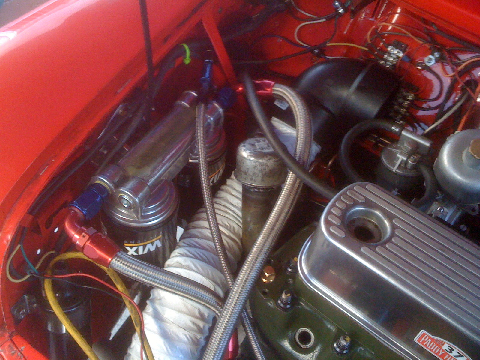
Mini
Coopers have a duct tube
going from the front of the car to an OEM heater box. When the heater
is
removed some racers use that tube to duct air to the back of the engine
where
the carburetors are. Usually the tube is just laid in there. I pushed
that
design by insulating the duct, installing a velocity stack for it
behind the
grill, installing a very tall valve cover to dam air trapped between
the engine,
hood, and firewall, and sort of bundling stuff up so air had to go
inside the
engine to vacate that space. I positioned the duct outlet with a 90
degree
plastic elbow so it blew directly into the velocity stack area. This
tube was
tested to flow 3x the air requirement of our engine at race speed. I
was
pleased to notice our “heater induction” and
“non-air-box-air-box” were working
fine when the car is on a track.
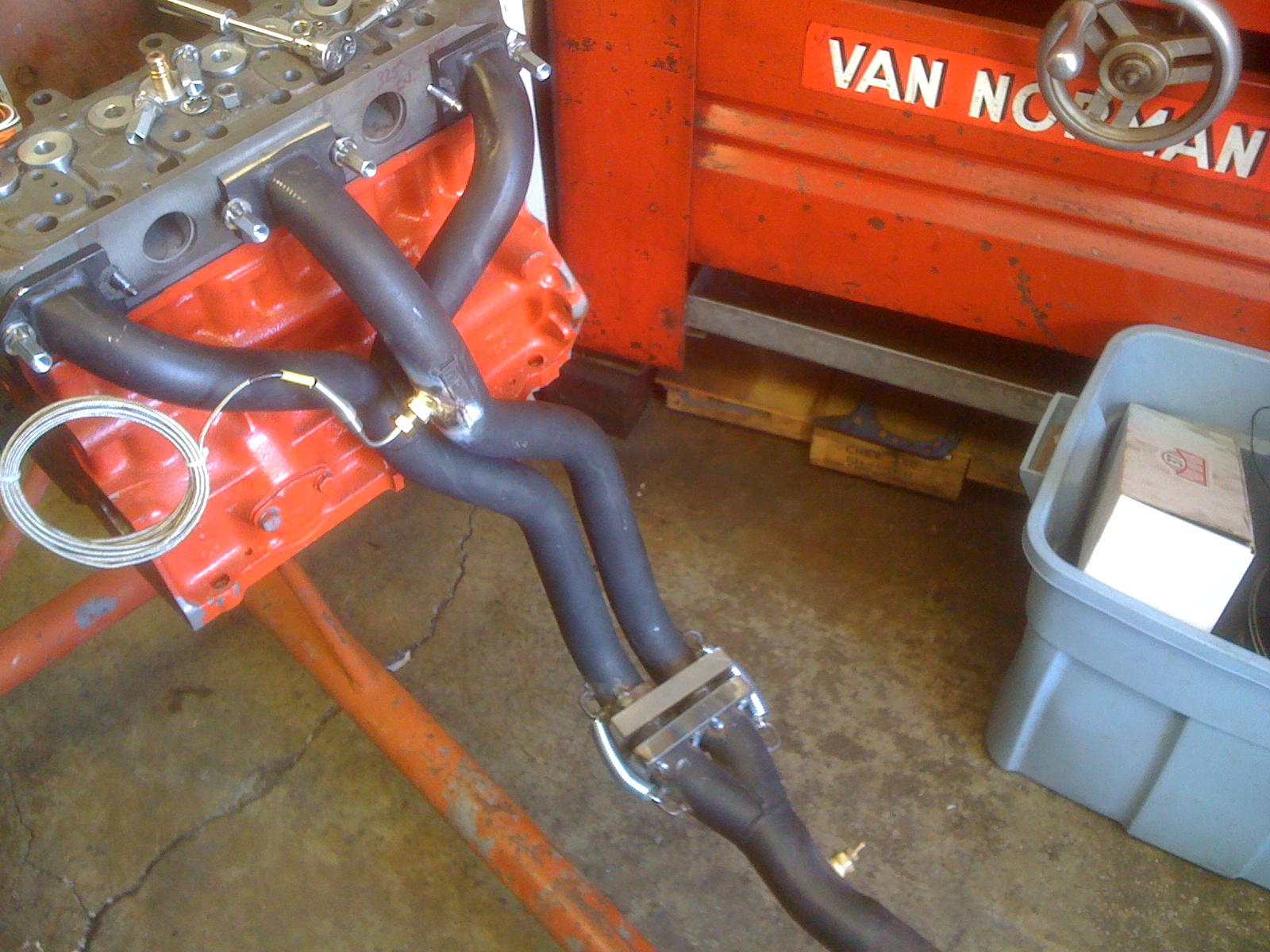
The carbs were sweating chilled water while
sitting
above a tight fitting header heat shield when the car owner came in
from doing
his qualifying laps. And I could hold my hand on the SU fuel bowls
without
burning it. At previous events there had been boiling fuel in those
areas.
Swain Tech white lightening coating worked real well for us because it
had been
applied to our headers and my custom heat shield in addition to the
entire
exhaust pipe.
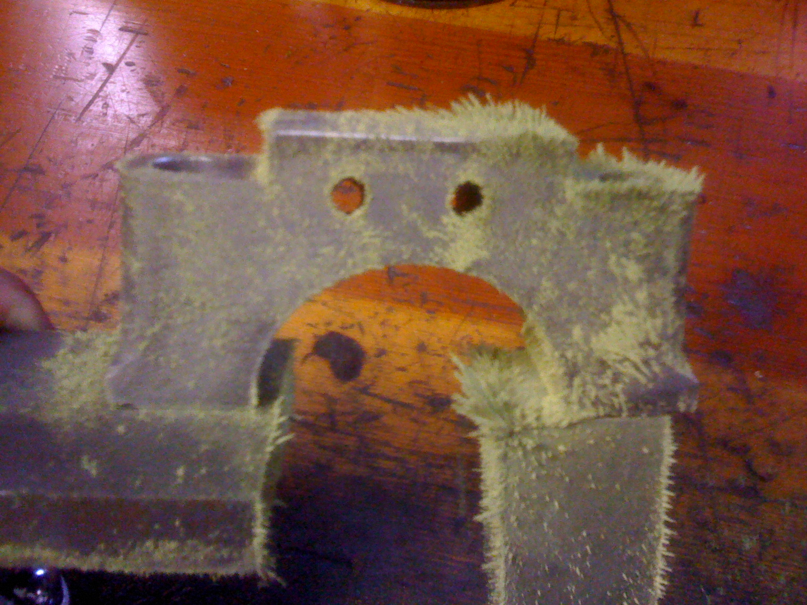
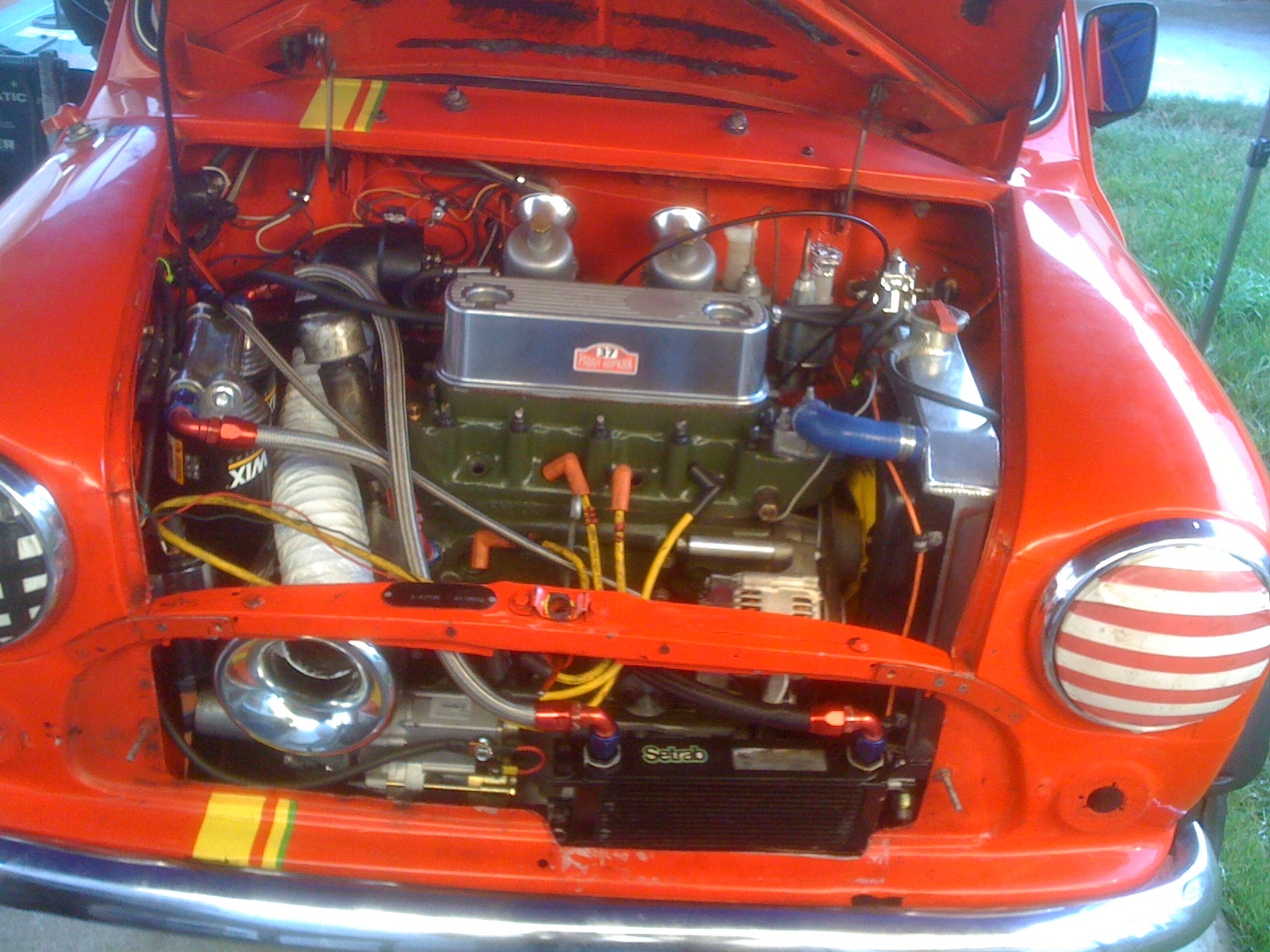
In
the
photo below notice how
closely the heat shield fits the fire wall of the car. I feel it is
important for
power production to keep hot things hot where they need to be hot and
cool
things cooler everywhere else. And if you can dam a bit of air into
doing other
good things along that path – so much the better.
As raced I put a length of roll bar padding between the engine sump and front cross member sheet metal to block air coming in the grill from going down under the car. Typically this is done with a front spoiler which is illegal for stock class cars. So I lowered our car to 3 inches between the pavement and oil pan – about the height of a spoiler - then blocked the air path so it had to go up around the engine and pass the radiator to exit, or into my velocity stack “heater duct” inlet. There are no rules about gasketing the engine inside its bay similar to the way Porsche does. We also bent our mandated stock grill louvers to angle air up-and-in instead of being flat obstructions. I feel the induction system for our engine starts about 2 feet in front of the car so its grill and engine bay entry is part of its carburetion path.
As raced, our 1310cc engine had 10.2 to 1 static compression ratio and produced 97 HP in one quick dyno pull at the track on its bone stock SU H-4 carburetors. Just off the dyno I literally bumped the distributor a small nudge ahead with my fist. Gary Hubback had given the RH carb a quarter twist more jet a few weeks before after listening to the engine pull through its range and when shifted on a long straightaway. We sent the owner out to win his main event with that as a “tune up”. I’m sure there is more power to be found if we ever gave this BMC engine a proper tuning workover. On the other hand, we beat a lot of cars claiming 120+ HP in their modified classes, in addition to winning the stock class outright, so maybe it is ok as is.
However
I feel more power isn’t
the key to making this Mini Cooper run faster. Front tire traction is
the
issue. Despite a very good driver, this
engine often pulls hard enough to melt our front tires after about 5-7
full out
laps. I’m thinking how engine heat blown out the LH fender well
by the radiator
fan needs to be directed up... thereby removing about 20 degrees of
temperature
rise off that tire while converting it to modest downforce...but aero
modifications are illegal in our vintage stock class….but racing
is all about
thermodynamics and aero control…It was a frustration the rules
would bump us
out of stock class if I removed glass headlights to help vent our
fenders,
which I really wanted to do.
This article was to cover just the British
Leyland engine build, but my perspective is; all related steps and
events told
here are also part of any vintage engine build up. To make serious
advances
over what an OEM 50 year old engine did requires testing and reworking
modifications
as an integral part of the job. A build for performance in the vintage
arena
cannot be just popping some pistons in and adding an aftermarket head
with a
catalog camshaft. A vintage rebuild makes more demands of its curator
than
that. And any engine is a part of a car
that only works as well as the systems which support it. Building a
race engine
is part of development of a car, and an evolutionary stepping process.
This car
had an engine when it came into my shop and I’ll build my client
a better
version of this one if he ever wants me to do so. And I’d improve
its support
systems again even further when I install it. One of the nicest moments
at the
Canadian / American Challenge races came in a few comments made by
vendors and
a couple of other car owners, that our car was “the most legal
Mini Cooper in
stock class”. I’m not sure how true that is, but it was
received as a very
complementary observation.
I’ve also held in my hands camshaft blanks
for
revised firing order “A+” engines that have custom
crankshafts to swap firing
orders around. I know that small groups of racers in Australia, Europe,
and
Canada are also running handmade titanium valve trains of various sorts
– some
in aluminum cross flow heads. I’d guess my version of this
classic British Leyland
engine is about 7-8 years behind secret current (2017) state of the
art. But it
sure was fun for my car’s owner, buddies, and I to do what we
did. I hope you
enjoy our story.
Epilogue:
Since the National’s
in 2017 this Mini Cooper was stored waiting for the 2018 season. I
prepared it
for an event in Sonoma set for early June 2018 but various health and
other
circumstances indicated the car should be put up for sale after we ran
that
race. However, it sold very quickly so was never run. A buyer in Los
Angeles
who has no current plans to run it is the new owner. He’s more of
a
collector-racer than a racer-collector who’s deeply committed to
several new
classes of electric car racing and production.
That is the majority of what this article will cover. Lastly, please
share any
photos of the engine, its parts, and any other shop images you feel
like
including.
Done
sir,
I enjoyed writing these paragraphs. I didn’t put much effort into
formatting
the pages or reducing the size of photo files. I figure after editing
your
staff would be much better at that than I. This long story tells about
half the
work and machine operations needed to build a strong running Mini
Cooper
engine. If you wanted more data because some gaps or jumps in narrative
pop out
to you, send a few more questions and I’ll figure an addition
out. Most of these photos were electronic
chatter
between the car owner and myself as we progressed day by day so many
were taken
with a cell phone instead of a proper camera. I hope they are useful to
you. But
if there is something else you want to see let me know. I’ll look
through my
client archive file to see what may turn up.
Thanks, and I look forward to hearing from you.
Best,
Greg
Agreed, Best regards, Ladd Fowler
Final
epilogue - This engine and article gained me a nominaton for "Engine
Builder of the Year" from Engine Builder Magasine. The nomination
didn't end up with a win over 11 other builders but it was still very
nice to be considered for the honor.