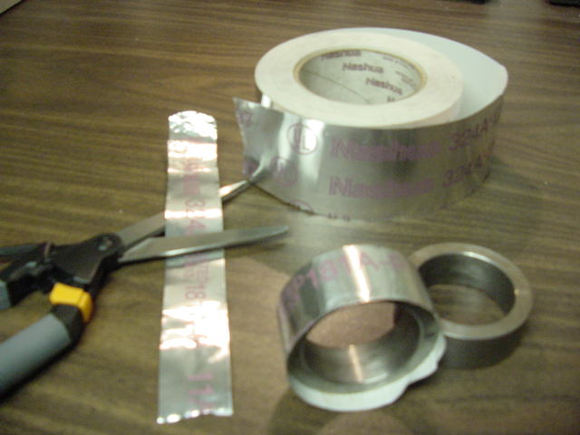
When using BHJ style 2 inch adapter rings that may be undersized for the application some metallic tape will shim them out to the correct size. Most rolls of tape are of uniform thickness and can be easily cut. It stays where it is applied and comes off easily.
Small Block engine building comments with Roger King about his United Kingdom 289 Cobra. Proof read 18 Sept 2016.I get the strong feeling this should be
published somewhere,
as it clearly has relevance for a lot of what happens now with the
‘old car’
hobby. The background context and way in which this science has
developed
is fascinating and makes for a very interesting, and informative read
for those
with a technical interest. Particularly love the Smokey Yunick story: first-hand records like that
are both
entertaining and valuable.
I have no remarks for correction of this (how could I have?)
and think it would be a very valuable contribution to the record for
those that
are looking for advice, so very happy for this to go on the forum if
possible.
Best wishes to all
Roger
Good morning, I’m the fellow
who provided parts and machine work to Roger, who’s engine is the
subject of
this thread. My name is Ladd. I wish to offer some thoughts to your
group about
engine break in and oil as they pertain to this build because many of
you are
doing similar work which may be improved upon. It seems there is a lot
of
interest in rear main seal issues too. I’d like to approach this
from a
perspective of posing then answering questions based on decades of
conversations with leading experts in various fields of automotive and
aircraft
engine performance. And from mention of historical data that leads us
to the
technology used today. While I’m just a lone guy in a
“hole-in-the-wall- shop;
I’m also a guy lucky enough to have been mentored by noteworthy
men and
intuitions who took time to invest in me with answers to many questions
so my
work could become better. Perhaps this bit of writing will be of
interest to
you while given in that spirit.
Engine break in was
historically needed as a “finishing” operation because OEM
production machine
work accuracy and surface finish quality were not acceptable for full
power
operation “off the production line”. This situation existed
from the beginning
of combustion engine technology until recently, perhaps arguably until
the last
decade. Thereafter improvements in OEM manufacturing virtually
eliminated need
for post assembly mechanical break in art to mate and seal engine
components. Along with benefits of
greater power being available sooner, great increases in engine
longevity have
been realized. Elimination of a wearing process to mate parts for
operation
generally called “break in” directly yields greater
functional life.
The question of
importance to
us now, as we renew half century and older engines is: how do we apply
new technology
to obtain the same benefit of more power, sooner and longer? And if
that
benefit is built into a remanufactured engine, how does one hang onto
it? I believe answers to those questions
are
fairly simple to understand, once presented for discussion, and are
found in
three general areas. They are; manufacturing processes and materials,
lubrication, and operation practices.
The small block
Ford engine
designed with knowledge accumulated by engineers in the late
1950’s,
then produced
starting in the very early 1960’s was considered
“modern” back then. It was
designed around improved technology, notably materials of cork / rubber
and
simple flat metal / carbon based center filler for gaskets, bi layer
bearings,
and improved alloy fully machined piston rings compared to engines of
the prior
decade. Prior engines used felt / leather, flat copper sheet or
asbestos,
Babbitt bearings, and low alloy poured cast ring technology. Those newer designs also used precision
manufacturing process, including select fitting instead of prolonged
break in.
However legacy
practices
needed to produce longer lasting engines and better power from older
designs
lead to unnecessary and sometimes damaging events when applied to the
then new
design. For example; running new engines for short time intervals with
cool
down cycles, use of very low temperature thermostats (or none at all),
and
introduction of abrasive compounds to “set the rings”
became obsolete, yet were
(and are still) part of some mechanics considerations when dealing with
a
rebuilt modern engine. Retrofitting solid copper gaskets and leather
oil seals
sometimes had significant issues back then, and would be nearly
unthinkable
today.
Break in oil and
oil
additives were also marketed and used frequently. It is my opinion most
break
in oils of the 1940’s to the 1970’s fell into several
groups. They were (for
the USA market) mineral oil based, had limited additives, and lighter
viscosity
compared against standard 30w oil. They functioned by providing limited
lubrication to the cylinder wall and ring set so those components would
wear
into a functional sealing condition (hopefully without seizing) while
holding
manufacturing debris / grit, in suspension. Holding debris and grit in
suspension was not good for bearings so that oil was drained as soon as
“normal” compression pressures were obtained. These
products were similar to
current Sunnen honing oil now used in cylinder finishing machines
worldwide.
The next group was viscosity enhancers which claimed to thicken and/or
improve
anti seizing risks in bearings when added to normally used oil
products. STP is
a brand name which comes to mind. It was not beneficial for seating new
rings
but was sometimes mixed with mineral oil in an attempt to gain
advantages
advertised by both products.
Another group was
chemically
active additives to enhance properties of normally used oils. They
contained
anti-scuffing and detergent chemicals to bond to grit and debris and
“high
quality” base oil stocks. It made these products expensive but
beneficial. Most
major vehicle and equipment manufactures had proprietary blends sold
through
their parts distribution networks. At the risk of oversimplification of
a
complex market environment and technical research it can be said this
class of
break in product evolved into additive packages now in modern oil.
Because these
products were
so effective as to become adopted worldwide in regularly used oils need
for
them as a break in supplement declined until some of them were removed
for
protection of emission control devices in the 1990’s. Resurgence
of break in
product marketing followed this genuine need for anti-scuffing agents,
as did
resurgence of folklore and legacy practices. I should credit Roy
Howell, a
Cornell graduate appointed as Chief Chemist at Red Line Synthetic Oil
Corporation, Dema Elgin a camshaft grinder
and
instructor at De Anza College, and Joe Mondello
who
founded the Mondello Technical Institute
for this
understanding gained in many conversations over many years’ time.
We are now faced
with
continuing technology advancements leading to production of
today’s modern
engines. Gaskets are now neoprene / specialty rubber blends or can
often be of
coated embossed steels. Specific
adhesives and thread locking / lubricating products are common place.
Tri-layer
and flash coated bearing are typical parts while moly faced and low
tension /
multi material ring packages are also very common.
In conversation
with John Erb, Chief Engineer, KB Pistons in
the 1980’s he related a story about building pistons for
Chrysler. They wanted
to know what to expect by way of variation between larger and smaller
pistons
in manufacturing so they could plan their select fitting procedures.
John told
them there was not going to be a manufacturing variation significant
enough to
warrant any select fitting. Chrysler did not believe that claim
initially, but
in the end found modern piston manufacturing to be so precise a legacy
practice
of select fitting was no longer needed in their assembly line. We, as mechanics, also have an even larger body of legacy practice which worked
on the ‘50’s to ‘90’s engines but sometimes
doesn’t work when applied to now current
designs, just as new parts technology may
not retrofit easily into older engines despite apparently fitting
mechanically.
Prudent selection of which materials work well with specific processes
used in
engine re-manufacturing is critical for successful power production and
longevity. Prudent selection is made by understanding history and
changes from
an evolutionary perspective. It also includes quality control
inspection
against known engineering standards. In our worldwide parts production
industry
manufacturing standards are often conflicted and obscure.
Oil, as a fluid in
engine
bearings, has two main functions; Lubrication and cooling. We have a
tendency
to focus on lubrication and “fixing” some falsehoods about
how that happens,
while forgetting about cooling so I’ll pose a historical scenario
and question
why that works as a lead in to modern design practice.
In the 1930’s
and prior years
many engines used dipper cups, splash, or vapor mist oiling for all
bearings
and friction points. There was no oil “pressure” as we know
it today – zero -
because there was no pump or circulations system. Yet these engines
were
capable of 2500 RPM and sometimes more, while producing a wide range of
horsepower outputs, including some supercharged applications. How did
oil at
zero pressure prevent metallic contact failure? The answer is capillary
action
as applied to the load capacity film strength of the oil. Let’s
do some
abbreviated, approximate, and very shallow math analysis.
Assume a crank rod
journal
size of 2.123 and a bearing ID of 2.125 by .75 wide. The difference is
oil
clearance of .002.
That yields a
circumference
for the crank of 6.67 inches leading to an area of 5.005 square inches.
Calculating a
circumference
of the rod bearing is 6.68 inches leading to an area of 5.010 square
inches.
The
difference in area being .0055 square
inches then leads to a volume calculation of .0055 x .002 yielding
.000011
square inches oil space volume. This converts to .00018 cc’s
of oil in the bearing. That isn’t much to provide cooling and
load capacity so
intuition says it needs to be circulated rapidly so it doesn’t
absorb so much
heat it chemically breaks apart into components no longer acting like
oil.
While dynamic
running
pressures against a connecting rod vary quite a bit for many reasons
1200 to
1750 psi in the combustion chamber is a good starting point for
conversation
and “bench racing” calculation. In a 4 inch bore engine the
piston has 12.56
square inches of area [3.14 x (2x2)]. That leads to calculating a
connecting
rod load of 12.56 x 1500 (average peak pressure) of 18,840 lbs. That is
quite a
big number.
Assume one half of
the upper
half of the bearing carries the combustion pressure load. This
assumption is
offered in place of calculus based on the geometry of the rod. Think-
the lower
half of the rod bearing isn’t in compression because it is below
the load
centerline. Just the upper half carries combustion generated loads. Of
the area
in the upper bearing half, a point at the top could be considered to
carry the
entire load while points at the side carry none of the load (being in
slip sheer
instead of compression). In actual fact that point load is spread out
by the
oil film so about half the area of the upper rod bearing carries
combustion
loads in an off TDC position.
Calculate half of
2.658
square inches to remove the lower part of the rod big end, and then
half of the
remaining upper bearing to find the load carrying portion, leaves .6645
square
inches to carry 18,840 lbs. This very approximately calculated load on
the oil
film is then 12,519 lbs. per square inch.
The following
excerpt from “Machinery
Lubrication”, in an article by Robert Scott, illustrates this
point.
“….The
mean pressure in the
load zone of a journal bearing is determined by the force per unit area
or in
this case, the weight or load supported by the bearing divided by the
approximate load area of the bearing (the bearing diameter times the
length of
the bearing). …… Automotive reciprocating engine bearings
and some severely
loaded industrial applications may have mean pressures of 20.7 to 35 MPa (3,000 to 5,000 psi). At these pressure
levels, the
viscosity may slightly increase. The maximum pressure encountered by
the
bearing is typically about twice the mean value, to a maximum of about
70 MPa (10,000 psi).”
It is my opinion
oil pressure
developed by the engine’s pump, wither it be 45 or 95 lbs,
when delivered via a .250 dia. feed hole isn’t going to counter
balance that
load without other factors being involved. So why have increased oil
pressure?
And why is there so much effort put into raising it? What are the other
factors
which really make an oil film lubricate a bearing?
A
great article on rod loading is found at:
http://www.eng.utoledo.edu/mime/faculty_staff/faculty/afatemi/papers/2006JMESShenoyFatemiVol220PartCpp615-624.pdf It is titled:
“Dynamic analysis of loads and
stresses in connecting rods”
P S Shenoy and A
Fatemi Department of Mechanical,
Industrial, and
Manufacturing Engineering, The University of Toledo, Toledo, Ohio, USA
The manuscript was received on 25 June 2005
and was accepted
after revision for publication on 6 February 2006.
And
an article covering how the oil film works
is found at:
http://scholarworks.rit.edu/cgi/viewcontent.cgi?article=1006&context=theses
Rochester Institute of Technology RIT Scholar
Works Theses Thesis/Dissertation
Collections
8-8-2013 It is
titled:
Analysis of Connecting Rod
Bearing Design Trends Using a Mode-Based Elastohydrodynamic
Lubrication Model Travis M. Blais
At the risk of
doing a huge
disservice to the scholarly papers’ authors, and by adding my
historical
perspective to their technical findings, our discussion of increases in
pressure for bearing lubrication can be summarized in the context of my
questions:
“Hot
Rods” in the prewar era
were melting babbitt bearings so needed to
improve oil
flow for cooling. The quickest and cheapest method to do that was
shimming or
changing their oil pump pressure relief springs to a higher value.
Increased
pressure correlated to slightly increased flow but also allowed
increased
bearing clearance while maintaining a functional oil film, which
clearance was
a far larger factor in increasing flow and cooling. Bearing clearances
were
then increased until their OEM pumps and available oil formulations
could not
maintain an oil film inside the bearing. Balances between oil film load
capacity, heat removal from the bearing, running clearance, and pump
output were
discovered by trial and error. That could be favored by higher
pressure, but at
the cost of parasitic horsepower pumping losses and generating unwanted
additional heat. Inconsistent
manufacturing, variation in oil products, lack of testing
instrumentation, and
fictional advertising hindered actual comparisons of successful designs.
At
this point real advances in bearing
material, pumps, and oil technology were needed to create higher load
and speed
bearings for high output engines of WWII. This research continues today
which
has resulted in modern bearing lubrication at far higher loads and
speeds than
the 1930’s and post WWII era allowed. Oil pump manufactures after
WWII started
to market oversize oil pumps in high pressure and high volume versions
so hot
rod engine builders could tip the balance of a stock lubrication system
towards
maintaining an oil film when high heat removal from bearings was
needed.
However better
oils, more
rigid bearings, improved surface finishes and higher temperature
materials
really allowed this advance. But our legacy habits of increasing oil
pump
pressure to attempt to gain a lubrication advantage persist when we
should be
gaining understanding, then implementing, modern changes to these other
factors
to upgrade our vintage engines. In my opinion, we as engine builders,
have
often placed the minor factor of increasing oil pressure into a role of
being a
major solution which limits our success in horsepower production to the
driving
wheels. Much of this information and history came to me over two
decades time
from Major William (Kelly) Owen, USAF, who among other noteworthy life
achievements participated in Indy 500 racing from the 1930’s to
1980’s, and was
Project Officer for the Cold Weather Test Detachment of the Proving
Ground
Command in Fairbanks, Alaska where they tried to make ground support
and
aircraft engines start, then run at full power in subzero temperatures.
An additional
factor in oil
pump pressure requirements is the effect of stroke of the crankshaft.
Think for
a moment of the crankshaft as a slinger style oil pump lubricating the
crankcase. Oil enters the pumps center along the main bearing feed and
is slung
out through the rod bearings to the crankcase. If rod bearing clearance
and/or
the oil exit path from the bearing is larger than the oil feed hole area, and if the slinging force is greater
than pump
supply volume then pressure inside the rod bearing will fall to zero
and the
crankshaft passageway can be sucked dry leading to bearing failure.
This is
generally called “oil starvation”. However oil starvation
failure should be
divided into two causes, the first occurs when not enough oil is
supplied, the
second when too much oil falls or is sucked out of the bearing. This is
similar to
“cavitation” which isn’t mentioned much in terms of
connecting rod bearings yet
is well understood in inlet side design of oil pump systems.
Because lubrication
of the
crankcase is totally pointless and detrimental to horsepower production
elimination
of cavitation inside the rod bearing by other means instead of
increasing the
oil supply is a more desirable method of upgrading an older engine.
These
observations and comments arise from discussion with Gary Hubback
of Los Altos CA, Bill Jones of Taylorsville UT, and Allan Lockheed of
Bolder
CO, who participated in teams running high power at Bonneville Salt
Flats in
record breaking cars.
This elusive and
complex
balance between pressure, flow, materials, and clearance was worked on
by many
prominent engine builders of the ‘60’s and
‘70’s. It was most notably codified
by Smokey Yunick in his “10 lbs
of pressure for every 1000 RPM” statement.
This guideline has taken on far more credence than current day
engineering might indicate is needed. In a December 2000 address at the
Superflow AETC Richard Maskin
was
asked what oil pressure his ProStock
engines developed by a competitor who said he was having bearing
trouble at 95lbs pressure
in the 9000 RPM
range. Richard replied his
national record holding small block engines ran 35 lbs
of pressure at above 10,000 RPM and his big block engines had 5 lbs more. Reference
AETC 11-13. Technology advances in the 16 years since then have not
mandated
higher oil pressures, although many people and teams routinely set up
engines
for 65 to 85 lbs maximum pressure. In my opinion they are giving up power output
advantages to be had at lower pressures when other modifications allow
that set
up.
Should we think of
a
traditional oil pressure gauge mounted in the output path of an engine
pump as
a pressure relief set point gauge? The moment an oil pressure gauge
stops
rising the pressure relief valve has opened. Further increases in pump
speed
simply dumps oil, heated by compression in the pump gears or vanes,
back into
the oil sump. It doesn’t even get into the filter loop. This is
lost
horsepower. Many engines achieve full pressure by 2000 RPM but are
raced at far
higher speeds. Reduction of pump capacity may be indicated after
testing and
specific research, while improvement in oil system circulation return
deserves
even more attention.
The V-8 small block
engines
we are rebuilding today from 50 years ago had oil capacity issues. Most
performance designs from the OEM would hold 6 or 7 quarts of oil. The
distribution at 5000 RPM was approximately one quart in each valve
cover and 2
quarts in the valley under the intake manifold, and as much as half a
quart in
the timing cover. This left only 2-3
quarts somewhere in the sump for the pump to intake then pressurize.
Many
engine builders fitted oversize sumps to “correct” this
issue. In my opinion,
improving oil flow back to the oil pan may have had a better overall
return in
investment, as seen in many European and Asian engine designs.
I believe oil
pressure should
be thought of as a catalyst in formation of a lubrication film, not the
principal force enabling lubrication, which is a property of the oil
and
geometry of the bearing. Once an engine has enough pressure to create
and
maintain an oil film, more pressure is detrimental. A watchmaker will
lubricate
bearings with a needle to which clings a drop of oil. When the needle
is
touched to the bearing oil instantly flows into the bearing clearance
and will
stay there for decades separating and protecting those surfaces without
input
of any pressure energy. The Holy Grail
of hot rod lubrication is zero friction, zero pressure, load carrying
bearing
systems. I believe high oil pressure is just a crutch we need to have
fun
running our cars today, while we figure out how build engines with near
zero
pumping losses. I believe some builders
have progressed along that path further than others.
However, I’m
reminded of an
occasion at a PRI trade show some years ago where Smokey Yunick
was promoting “Prolong Oil Supplements”; additives alleged
to reduce friction
so effectively the oil could be drained from the crankcase and the car
would
still function. Prolong had bought a new Dodge Viper, treated it with
Prolong,
drained the crankcase, then had a famous race driver hot lap the car in
a TV
ad. About a half dozen of us cornered Smokey at a table asking him what
happened to the Viper….. After giving us the promotional pitch
in a few
different ways and our continued pointed questioning he finally broke
out with
“what the hell do you think happened with no oil”. It was a
fun day to be there
for that “‘revised” marketing pronouncement.
With
this
background information posted I’ll go back into Roger’s
email threads to make
specific comments in red mixed into his text in black.
I got into the rear main
seal. Glad I did. The lip is disintegrating, with a couple
of nicks
here and there, and it feels very brittle and hard. I can’t
remember how
old the gasket set was when I assembled the engine, I guess it could
have been
on the shelf as much as a year. Then the completed engine sat in
its
frame for nearly two years due to unavoidable delays and I guess this
combined
is what has caused the problem. This
is very odd and I’ve not seen one go like this before. I
usually clean
with a lint-free paper wipe, no solvents, install and then apply a
lubricant
(oil, assembly lube) before laying the crank in place.
This
isn’t normal.
I have neoprene (or whatever that material actually is) rear seals from
old
gasket sets that are 15+ years old and have worked fine. And when you
think about
it, seals in service last for longer than that. If you are seeing
hardening to
the point where it actually feels too hard then I’d suspect some
chemical
action or heat changed the seal material. Did it get near or in
carburetor
cleaner? That is a big no-no for seals.
So,
it’s a couple of
days of very careful cleaning before it all starts to go back together
again.
I have a new standard Melling oil
pump and
pickup to go in (using the ‘old’, 200-mile, ARP heavy duty
drive shaft), even
though the ‘old’ pump has only done 200 miles. I
thought I’d take that
precaution even though everything is new. As usual I have stripped and
measured
the new pump as I trust myself more than whoever put it together.
I’d
have no
hesitations reusing the old pump. It is qualified now as a known good
part, not
hurt in any way from 200 miles. The new pump may be defective –
or calibrated
differently- so has less value towards solving a mystery because it
introduces
new variables. And the new pump will shear off metal bits breaking in
that the
last pump has already rid itself of.
The
pressed-steel sump (oil pan?) I
have is not a great fit. I should have worried more when I found
I had to
use a thick bead of silicone on the pan side of the gasket for the
entire
surface that fits around the rear main cap - with the pan dry
bolted-down with
rubber gasket in place, you could see plenty of daylight through the
gap where
the curved section should have been compressed. I have another
that I
have dry-fitted to a spare block and it is very much better, so that is
this
week’s job.
Oh my.
This is
serious parts mismatching and can lead to oil system problems. The
rubber seal
on the main cap depends on compression against the cap to seal between
it and
the cap. A leak will occur despite bonding of the silicon to the rubber
and
silicon to the pan metal if there is no compression against the cap.
A
“thick bead of silicone” in that
area is
also contrary to good engine building practice because it can break
off. If any
of the silicon is “missing” from your bead upon disassembly
it would be wise to
strip the entire engine oil galley system looking for it. Start in the
oil pump
inlet screen. From there, look in the oil pump relief valve. Then some
may have
gone into the filter or cooler plumbing which is usually the end of
migration
for a modified oil system. I say “usually” knowing
I’ve found bits of silicon
in the ends of pushrod tubes plugging up the rocker arm feed holes. I
wonder
how those gobs of silicon got through a lifter body but they did. If
your
system doesn’t have a plugged oil filter pressure relief hole
(and there is
little reason to block that hole in a stock system) then the silicon
gobs can
go anywhere in the engine.
I’ve
had a few oil
pans that didn’t fit too. That is so vexing and troublesome
I’ll sometimes make
a pan or modify one that fits the rails and end seals nicely to avoid
buying
one.
Latest brief update - Popped the engine
out
today, mounted
it on the stand and rolled it over - it’s not the oil pan,
it’s the rear main seal.
I don’t know why a new one has failed so soon. There
has been a
spectacular leak since the first trip out, which is now unsustainable,
½ pint
in 50 miles with oil dripping from everything. It’s
radiating out from
the crank but luckily has not got on to the clutch. I can see
that the
faces of the pan gasket are dry so that has been doing its job.
Let me interject here a few
comments about how
important proper PCV and KV systems are. Going back in time; before
very early
days of “modern” crankcase ventilation, prior to the
1960’s, there was one
system. “KV” stood for crankcase ventilation and it was
comprised of a road
draft tube and vented valve cover breather cap(s). The system was
designed to evacuate
the entire volume of blow by gases at maximum engine speed by way of
venturi
action of air flowing over the end of the road draft tube from vehicle
velocity.
It was vented by valve cover “breathers” allowing entry of
“clean” under hood
air into the engine. It was understood blow by gases and fumes from
burnt oil
were detrimental to engine lubrication so needed removal.
I’ve stopped work for the
night
but will loosen the mains
caps and remove the rear one tomorrow to have a look at the seal
itself.
I should be able to change it with the motor on the stand - I
don’t want
to remove the crank, as that would mean disturbing the heads and
pistons etc.
The question is, why did it fail,
though?
We shall see (hopefully)!
On 21 Jun 2016, at 19:56, lfowler@fowlerautomotive.com
wrote:
Roger,
could I ask you to hold off on re-installing your engine until I get a
chance
to tell you how to test that seal for sealing while on your engine
stand?
Thanks, Ladd
A few years ago I did some
engine program work for a team running a Toyota off road truck. They
were
switching from a 22R series 4 cylinder engine
to a 5VZ-FE
series V-6. They didn’t have a PVC system which would transfer
ahead so
neglected to install one. At racing speeds the engine started blowing
cam and
crank seals out of their housings causing massive oil leaks. I helped
them
build, then get a PVC - KV system installed and working, but rear main
oil seal
leaks persisted that were difficult for
their team to troubleshoot. Eventually I discussed, and then showed
them how to
check a rear main oil seal on an engine stand before it is run.
This method is from an old
1960’s A/C Delco emission testing manual and can also be found in
Cummins
diesel engine service publications.
First you fully assemble the engine with all covers and
manifolds in
place. Then you block known leak areas like road draft tubes, crankcase
breathers, oil dipstick tubes and so on. Then you pressurize the engine
to 3-4 lbs with air and spray the rear
main (or any other gasket
area) with soap solution looking for bubbles. Remember the engine will
not hold
pressure. It will leak down past the rings so air will be lost out the
manifolds. This is normal, but fizzing or bubbles at seals and gasket
interfaces indicate a site where oil will be lost from the engine in
service.
On old Ford engines with
dual
valve cover standpipes for breather caps it was very easy to simply cut
a
bicycle tube in half, hose clamp each end to a valve cover standpipe,
and then
use the tube’s fill valve to pressurize the engine. I’m
sure you can invent
something similar for your Cobra. I’ve also used the oil dipstick
tube as an
air pressurization point.
A bit of trivia from
Caterpillar engine company is their engine paint denoted as “Old
Caterpillar
Yellow” contains lead and other additives designed to seal gasket
oil leaks
externally. My understanding is workmen on 1970’s engine assembly
lines were
directed to liberally paint all engines on all surfaces to prevent
leaks. Heavy
painting as leak prevention against warranty claims was also taught and
practiced at the Cummins engine training facilities when I attended
there in
the early 1980’s.
On Tue, 21 Jun 2016 19:50:38 +0100, rsk@ac289.com wrote:
I
have stopped using Felpro since I had a
very odd
coolant leak on the Mustang’s intake manifold 8 or 9 years ago.
The
built-in silicone elements of the gasket had kind of melted, leaving
coolant dribbling
down the front of the engine, very hard to spot where it was coming
from.
Luckily it did not go the other way into the lifter valley.
I only
use Reinz now and have had no problems at
all with
them.
All
gasket manufactures had leak problems with silicon “O” ring
gaskets in the late 1990’s early 2000 model years. It was caused
by
incompatible chemistry in antifreeze. The debate continues today long
after
antifreeze use charts have been published by major manufacturers and
gasket
manufactures have changed the formulation of their gasket materials. A
portion
of that problem was different vehicle manufacturing standards for
coolant
applications in a
world market.
From: rsk@ac289.com [mailto:rsk@ac289.com]
Sent: Tuesday,
June 21, 2016
11:26 AM
To: lfowler@fowlerautomotive.com
Subject: Re:
Oil leakage
Yes, I think the
synth is the
best option. I did remove the crank with head and pistons in
place, and
even gave my dear wife the privilege of being involved - she guided the
(appropriately protected) rod bolts around the crank journals during
replacement. I’ve put a two-part seal back in, a Reinz
brand new one, ⅜” offset and a tiny bit of RTV on each end and on
the cap
mating surface. Can’t get rope seals in the UK, and
I’ve long lost the
pin from the rear main cap.
I
believe you need
to check a couple of other things too.
A quote
from Albert
Einstein is “insanity is doing the same thing over and over
expecting a
different result”. When I hear of
people
replacing a rear main seal over and over again I have to wonder if
there might
be some other cause for a leak than being misassembled.
I know
many tens of
thousands of rope rear main seals have been replaced with updated lip
seal
style neoprene assemblies. However when the rope seal engines were
produced manufacturing
tolerance of the rope seal area were not very tightly controlled.
Manufactures
counted on the rope seal material to conform to any geometry their
tools cut.
Now, decades later, seal manufacturers are making a “standard
part” which might
not conform to the block and cap tightly enough to create an oil proof
OD seal
while being perfectly acceptable on the ID against the crankshaft. Yet
they
feel “OK” sliding into place. Or the concentricity of the
rope seal area may
not be centered well enough for a lip seal to function. And the new
seals
themselves may have excessive manufacturing tolerances on the OD
because they
come from plants all over the world that each does some details a bit
differently. Perhaps these issues are root causes for oil leakage
falsely
blamed on joint offset or misapplication of gasket sealer. I may be
incorrect
in saying no OEM offsets lip seal gaps in production. I believe it is a
service
procedure, sometimes of limited value, because if the OD crush of the
seal is
reasonably correct its ends will butt virtually oil tight and do so
without any
additional sealer.
In the
Ford small
block engine the rear main cap has a large window for oil drainage off
the
bearing. Unless that window is blocked by a mis-fitting
oil pan, gross misapplication of silicon sealer, or dramatic over
filling of
the oil pan; oil pressure coming out the edge of the bearing falls to
zero
within a few thousands of an inch of the bearing edge.
The
crankshaft has
a slinger ridge which then guides oil from the bearing’s oil exit
area
into the
drain window. Its forces of operation are parallel to the rear main
seal lips
so don’t contribute energy to the oil in a way to force it past
the seal. Space between the oil slinger
cavity and rear
main seal is mostly empty - free to drain.
If rear main
bearing
pressures on the oil are relieved before it gets to the seal what
moves oil
across seals lips blocking that path ? What adds pressure to the
oil so it seeks
a lower
pressure area outside of the engine?
A
general answer is
crankcase pressure from blow by gases. This may be true and is easily
tested.
However leaks persist even when this possibility is reasonably
eliminated. I
think it is wise to consider the possibility some pumping force created
in the
space between the crankshaft slinger and lip seal in the engine
overhaul
process acts on the oil so very low or
perhaps near zero crankcase pressure is added to and becomes enough to
cause an oil
leak that
didn’t exist before. Or a leak that the more robust OEM rope seal
closed successfully.
I
suggest checking
and correcting the length and sealing quality of new replacement
flywheel bolts
may lead to stopping oil leaks in the vicinity of rear main seals. I
believe if
that bolt is too long it will grab oil in that cavity and spin it
around just
like a rotor vane pump does. The “pump” inlet becomes the
slinger exit area while its
exit is the drain window. The upper seal area can become packed
with oil
waiting to drain out the window which also leaks past the seal. Bolts
that are too short cause a
similar but
less intense pumping action because of the void in the crankshaft
threaded
sections. This will be an RPM speed sensitive leak.
When we tested the Toyota
team’s engine it had
signs of oil radiating from the crankshaft on the flywheel clutch side.
A
bubble test showed leakage out the bolt heads. No sealer had been
applied to
new grade 8 bolts purchased at an industrial supply house instead of
getting
OEM bolts that had sealer pre-applied, a flat shoulder under the bolt
head, and were “one time use” fasteners. Sealing the bolts
was an easy
fix for something
that had vexed their team for many months.
On Tue, 21
Jun 2016
18:27:06 +0100, rsk@ac289.com wrote:
I like
this idea of
personal tech service at a high level, I might get used to it.
Hi
Roger, It
is a good thing to do for me and for you. About a third of my income
comes from
consulting now and I've met some really interesting people doing some
pretty
interesting things. I hope you figured out that the crank can be
removed with
the heads and pistons intact in the block. I'd put in a rope seal. I'm
writing
on a longer explanation now. Go for the synthetic oil.
Don't
be afraid and never look back. Lol.
Ladd
I’d
have to say that
top of my list of questions is, should I go to the full ester synthetic
now
(200 miles), and not worry about the ZDDP on the flat tappet cam?
Whilst replacing this
rear seal, I have been through the engine completely and it looks
great.
It is a tribute to your skills, Ladd, that
everything fits so nicely and neatly and all the bearing surfaces have
such a
uniform polished pattern with no signs of scuffing or uneven wear.
I can
live with the oil pressure, although
I’d expect it to
drop a little bit more with a full synthetic. Roger
Thank
you. I
appreciate your work in my shop and conversation about the things we
do. I
believe you can see that traditional issues of engine break in,
bearings,
gears, chains, and valve train have already “broken in” in
less than 200 miles.
I think in other emails you have said the engine runs smoother than any
V-8 you
have previously owned so my guess is the rings and cylinders are
working well
also. As I mentioned elsewhere this engine was prepared with modern
methods and
parts so would “break in” very quickly, say in less than 10
minutes or 50
miles. So go for the full synthetic oil. Don’t hold back.
In the
early 2000’s
I went to a technical conference sponsored by Joe Gibbs racing where
oil (among
other things) was discussed in detail. Of the professional engine
builders
there we all had lost a few camshafts to lubrication failure in prior
years.
ZDDP was discussed and we were assured the Joe Gibbs product had enough
to meet
our needs “off the shelf”. This was possible because of a
loophole in the EPA
laws for small quantity manufacturers of specialty blends. It was also
possible
because different standards existed for HD truck oils than passenger
car
lubricants. A consensus was quickly formed that Shell Rotella
and Chevron Dello diesel truck oil were
acceptable
alternatives to expensive additives. And later on I learned that
Redline and
Royal Purple products were “correctly” formulated for
applications with high
camshaft to tappet loads. Whatever the equivalent products are in the
UK will
work fine. I kept your valve spring tensions low deliberately so
troubles
would not
darken your doorway but provided a set of race springs in case you
wanted to
push your RPM limit up to 7000 after a while.
I am
also reminded
of a 1980 conversation with Henry Styers,
then a
regional GM training instructor about small block GM camshaft failures.
I’d made
some cocky comment about being able to fix any cam problem GM cars had
– just
send them over to my shop and I’d put new parts in from
after market sources. Whew-
big mistake. He turned around and told me the problem was bigger than
GM so who
was I to mouth off that way about things I didn’t understand. I
believe he’d been
an Air Force DI, then officer candidate instructor in WWII, so his
attention to
disarming my cocky attitude was detailed, complete, and expertly done
with the
grace of a southern gentleman.
I
learned from
Henry that GM was fully aware of camshafts failing because of oil
issues
some years
prior. They understood where government regulations had driven
the oil
industry, and were already testing valve train durability extensively.
GM’s
answer was an additive sold over their parts counters and provided to
dealership
mechanics when replacing engines. He also told me GM produced some
blocks where
the lifter bores were not angled correctly which caused failure. These
were
being quietly replaced under warranty. He denied any metallurgical
issues with
cams and lifters themselves. Henry ended on two points. First, whoever
makes a
car part can do it anyway they want to – it is their right to
innovate, but the
market would tell who did the best job, and he believed GM was the
premier car
company so had the best parts. Second that my invitation (as an
independent mechanic durning a GM educational promotion) to attend a
single training class was extended
indefinitely at
his personal recommendation. So I attended GM school as often as I
could until
Henry’s retirement in 1983 by which time I’d attended
nearly every class
offered.
Henry’s
passion for all things GM was
counterpointed by Orion Yando’s
passion for all
things Ford. He was Ford’s western region general manager. I
attended High
School with his son Dick so observed first-hand how dedicated he was to
advancing Ford products when occasionally in their home. Later I
attended Ford
Industrial engine school finding the quality of teaching staff
excellent, and similar
to GM school. A take away lesson I learned is, passion for a
company’s
product and detailed
knowledge of the product go best when hand in hand.
I have a question on oil pressure.
We
went with std
main bearing shells on the
crank, and you gave me the options of building the rod bearings looser
(all std) or tighter (std
and +1thou)
or tight (all +1thou). I have gone with the tight option, using
the oversize
shells upper and lower in the rods. I’ve now done around
200 miles in the
car, but the oil pressure seems a little low at 20psi hot idle (650rpm)
and
45psi hot at 3000rpm. I’d welcome your thoughts on this,
although I know
these are acceptable figures for a small block Ford.
Oil leakage
past the tappet body is important to understand. It can be calculated
in ways
similar to connecting rod clearance but we don’t know how much
oil actually
flows past the calculated space so this is a comparison of clearance
volumes,
not gallons per hour. The Windsor Ford tappet is .874 dia. (smallest)
and .8745
dia. (largest) Manufacturing tolerances are very closely held so
anything
outside this range should be rejected as a defective part. If we accept
.0027
as a clearance wear limit, oil at the tappet needs to pass a .048 cc
clearance
space. Circumference = 2.75 inches, passing approximately .200 inches
twice
(upper and lower tappet bearing areas) at .0027 clearance. Sixteen
tappets
would have .768 cc’s clearance volume – not much
considering pumps are rated in
gallons. However tappets erupt a literal
caldron of
oil in operation which needs to be returned to the sump as rapidly as
possible
through over sized drain holes and scraped off the crankshaft.
I am concerned that as the engine beds
in
these figures may
go lower. I’m running a mineral 20W-50 (high ZDDP) to run
in, but was
planning to go to a 15W-30 fully synthetic later. I think that
may show
an even lower pressure though, so may stick with the mineral.
I’m a born
worrier, as you can see!
I’m
glad you set your crank up to the
tighter
specifications. The photos of your Plastic Gauge clearance checking are
ok. There is
modest
controversy about its use. When I started using Plastic Gauge in the
1960’s
the directions
were to apply it to clean and dry bearing journals for the most
accurate
reading. That became problematic in my opinion because what you are
trying
to
figure out is oil clearance not air clearance. And putting Plastic
Gauge in dry
created a problem getting it out again. I was always putting a dirty
fingernail in
there against a very clean crankshaft which bothered me a lot. Not to
mention
how I felt about scraping it off a new bearing shell. So now, a few
hundred
feet or more into use of that product, I always put it against an oil
wet
crank. I did noticed your pattern was a bit short though. I’d use
a longer
piece so it lays
over the bearing shell edge on both sides. Seeing taper in a journal
with
plastic gauge is possible, but so is seeing a twisted rod, bent rod,
error from
torquing the rod cap (which unavoidably pressures the journal so the
plastic
gauge needs to be placed at 90 degrees to the cap parting line) and a
couple of
other bad or possibly illusionary things. Measuring bearing fit with a
micrometer has limits of about a half thousands
realistically, which is the same as plastic gauge. My opinion is both
options
have a great place in engine building but don’t trust either one
on its own to
be a final indicator. And I’ve nearly given up getting Plastic
Gauge out. Just
leave it in there. It is low temperature material so vanishes when an
engine is
started doing far less damage than the dirt under my fingernail might.
I
noticed in a
forum thread your idle speed was 650 RPM. That is too low. Light oil
will not
pump well at that pump speed. Remember your oil pump runs at half
crankshaft
speed. And it depends on constant RPM to keep pluses and flow going
smoothly.
Bump that up to 800 or so. Everything will work better. I’ve
noticed many modern
engines using light oil have pumps running at crankshaft speed. There
are
reasons for doing that which we need to think about before we run light
oil by
just pouring it in older engines.
I
noticed in a
forum thread a comment about 360 degree
oiling not
being necessary on a Windsor small block. I agree, but pose these
questions:
What happens when the oil passages at the main bearing shuts off every
36
degrees (180 degrees divided by 5 main bearings) sending a pulse
echoing back
to the oil pump? And what happens to cavitation of the rod bearing when
smooth
flow is interrupted? I think the answer is "nothing good". Which leads
to
another
question: why didn’t Ford put in 360 degree oiling from the
start?
An echo
back
pressure spike will rattle the pump gears and rattle the pump drive
which can
rattle the distributor gear drive harmonically. All that is part of the
"nothing
good" answer. An interruption of pressure and flow to the rod bearings
means
energy is dissipated doing no good while energy is later needed to
restart that
flow to get back to whatever level it was at. This is wasteful; and
risky if
conditions are marginal. Ford made a choice about their main bearings.
A 180
degree oiling channeled upper shell could supply the rod bearing for
stock use.
The 180 plain shell lower could carry more combustion chamber pressure
load
allowing the entire bearing to be designed narrower and cheaper. So
that is
what happened. For economic reasons 180 degree oiling was chosen, not
because
it was a better design. But that was then and this is now. To get from
180
degree oiling to 360 degree feed of the rods takes another $60 main
bearing set
to rob the upper shells from and 10 minutes with a cut off wheel to
re-notch
the main web for a modified bearing tang location. The question becomes
then:
is that security and performance benefit worth it to you?
The only thing that was not normal
during cam
break-in was
that the motor got excessively hot - bright red
glowing cast
headers - which was down to a distributor problem giving
retarded
timing. Cam break-in was interrupted a couple of times to try to
sort
this, which was finally achieved with a different distributor. I
can’t
see how this would affect the crank seal, but all is now assembled
again by the
book and I will report back on progress.
Heat in
any
cylinder head is removed by water and oil and exhaust gases. Oil from
the
rocker arm drips down the spring and across the head surface moving
heat to the
oil pan and out to the cooler from there. Some engines are rebuilt so
oddly
with high pressure and / or high volume pumps they flood the valve
covers (and
tappet valley area) and run out of oil in the pan to pump to the
bearings.
These engines don’t last long so to “fix” that issue
some builders restrict oil
flow to the valve train knowing roller rockers don’t need more
than a mist of
oil to function…. More oil stays in the oil pan – sort of-
It is just pumped in
a circle from pan to pump to pan via the pressure relief valve, while
gaining
heat. The small amount of oil running across the head becomes
super-heated and
quickly degrades. That heat and degraded oil hardens all
engine seals over time.
Some
engine
builders went so far out on that limb after restricting oil flow to the
valve
train and fitting over sized oil pumps and sumps they installed bypass
lines and
spray bars directed at the valve springs to cool them. In my opinion
simple and
OEM over oiling the rocker arm cannot hurt anything, but under oiling
the valve
spring is death for the spring. So my position is; don’t add
valve train oil
restriction, improve oil flow drain back instead.
Evaluation
of how
much heat goes into a valve spring lower coil from the exhaust port is
different for various points in the head. And some heads put the
springs in
very bad spots for staying cool. I have noticed when testing new spring
sets
they form a bell curve of pressure distribution. I install them so they
do
equal work by shimming installed height to nearly equal values +/- .015
then
putting the slightly stronger springs found in the bell curve
distribution into
the slightly tallest remaining positions. This equalizes heat generated
by
spring compression in operation. I adjust that procedure if I’m
using a dual
pattern cam.
The goal is to make the springs all last an equally long time. If I
cannot make
a “set” of valve springs from 16 I’ll buy another set
to increase the number of
springs in a favorable portion of the bell curve distribution. Isky makes really good valve springs at a racer
/ hot rod
level. Comp cams springs seem of inconsistent quality, but getting
better. When valve springs are run very hard, hot, removed, and
retested a bell
curve
distribution of pressure has gone away and more random pattern has
formed,
although sometimes that pattern is distinctly exhaust or intake side
denoted. Adding
oil deflectors to the top of rocker arms so the lubrication spurt is
directed
down into the pivot and into the spring coil (instead of up onto the
valve
cover and wasted) is very helpful. Ford did this on their big block
industrial
engines.
Thanks,
Best of
luck to you going back together and when on the road.
Ladd
Thanks for all your work in preparing
this
reference work.
It is really helpful and should be there for others to read.
Oh well, it seems we’ve just left Europe - time to get back
in the workshop and put politicians out of my mind for a while at least.
Hi Roger, glad you are
running
again. I enjoy
hearing my tips helped your efforts succeed. I’m not sure why
your oil pressure
improved. I’d guess the oil which was drained out had a bit
different thickness
(actually thinness) so didn’t pump the same. If you get a good KV
system
installed I’d recommend going onto an oil analysis program for a
year or two so
you don’t over change expensive lubricants while discovering how
seldom that
needs to be done in today’s vehicles. We found on the IMCA car,
even running in
the dirt at very high oil temps of 300+ F, Redline synthetic oil would
not
break down until half the season was past. Dirt ingesting from open
breathers
was an issue though. In a half dozen other engines I’ve had on
synthetic oil,
with monitoring, (BMW, Honda, Ford on Mobile I) sometimes unbelievable
(to me) change
intervals (8 to 10,000+ miles 3 years) were discovered to be fine
chemically.
These engines have all gone great distances in high speed/hard service
and are
on their second or third hundred thousand mile go round without any
lubrication
wear issues or any “overhaul” service what-so-ever. I
believe data gathered in
oil analysis can lead to economic savings (and catch early failures) so
recommend it while clients get their new engines figured out
operationally.
Rear axle unit’s out now as I am
changing the gearing from
3.07 to 3.31. I have a couple of days to get the new one in and do a test run.
Ok
Roger. That is
it for me. I think I’ve covered my build theory and practice
enough for anyone
to wade through. I’ll send this to you first for comments and
corrections then
maybe post to the Ford engine forum.
Notes on Piston Ring Sealing January 11 2014
Hi Roger, Kevin passed this link on to me so I thought I'd let you know we follow your thoughts and ideas over here pretty close. And we hope your build is going well. If I might add a few stories about the engine bearing and glaze to comments you posted, maybe something might "ring true" for the group and move all of us to a better understanding.
In the mid 80's I was running a dirt track stock car under NASCAR rules in the Winston West series. I was very lucky to get firsthand advice from manufactures of rings and bearings through their regional tech specialists. Their position was (is) moly faced rings if put against a properly surface finished cylinder wall "seated" virtually instantly. And engine bearings assembled against a properly finished and sized crankshaft required no break in period. After wrapping my head around those statements I stopped trying to develop a perfect break in process and instead devoted additional effort into improving the surface finish and size control of the parts I put into my (and my clients) engines.
This effort put me squarely into questions about cylinder wall glazing. At the time Smoky Yunick was just near the end of writing for Circle Track magazine so I posed the question "what is cylinder glaze and how do you form and control it" for his last technical column. He answered my question in a partial way saying it was a product of the oils and additives in the engine formed when exposed to heat. However we continued exploring that answer privately the following year at the PRI show. His further comments reveled to me the importance of thinking through some pretty self-evident issues, among them the fact that an engine’s cylinders cannot function well without a glazed or very smooth surface for oil film to work with. And many engines assembled without any piston rings will still pump more than 50% of their designed compression pressure. Therefor controlling formation of glaze is the primary goal of a modern break in process, not the final resizing of rings or bearings.
This put me in a hard spot to reconcile historical engine machining folklore vs. modern manufacturing processes. And got me thinking about how to form a properly glazed cylinder wall. I searched a lot of SAE information and talked to several nationally known winning engine builders finding no single product that everyone successful used. I was lucky enough to trade Joe Mondello some intake manifold machining fixtures for a month with Joe in the early 2000's. This enabled attending his engine building and porting school while picking his brain on this subject (and many others) too. I can say with near certanity that nobody at the national level uses WD-40 to lubricate piston rings or bearings for final assembly, but it does make a fair rinse off product for fingerprints and invisible airborne contamination. I can say that some people at national levels use assembly oils which have the following characteristics: increased clinging power, increased moisture tolerance, enhanced load capacity, and ash free burning. My choice for final engine assembly (except in the valve train) has been 2 stroke outboard motorboat oil for a long time. It seems to work for me and is consistent in properties with what some of the best in the business are doing. And most of that gets flushed out of these vintage engines before starting by an engine prelube procedure using Dello 15-40 diesel truck oil.
Two interesting comments to close with follow: the first from a SuperFlow Engine Conference in the late 1990's by a presenter who builds Pro Stock engines for clients and their companies lease program. He said with hot honing and bore plates; cylinder geometry is pretty much perfect for the rings to seal against. And the rings barrel face and composition are pretty much perfect for the cylinder material. Those combinations are well engineered and known. So the real challenge to overcome to produce maximum compression and power is in perfecting the seal between the piston lands and the ring. So they brought their piston production into their facility away from "outside vendors" and buy box stock rings now. And the last from Smoky Yunick who told me most of the problems attributed to glazed cylinder bores are actually gummed up rings stuck in the piston lands from incorrect assembly lubrication (or clearances) which cannot thereafter seal the bore properly (I think that came from testing either for or in GM's engine lab in the 1960's).
A final point to consider is every manufacturer of engines I am aware of specifies some variety of SAE or API rated engine oil for ring assembly including HD truck, marine, and aircraft. The days of folklore about non-detergent oil and other mystery stuff are long gone.